Planing benches - woodworking benches. Reismus wood craftsmen Vibir robot mode
The double-sided planing bench Logosol DH410 is very similar to the PH260 machine. The layout is based on the same principles, most of its components are identical to PH260, then. This is a very durable workbench with a working table and large motors for cutting and feeding. However, new knives and cutting heads are also worn out.
The advantage is that the DH410 uses two cutters instead of four. The four-sided planing is finished by passing the board through a plank, with a cob-shaped planing of the board and a further board to dimensions of 310 mm in width and 100 mm in height.
DH410 is primarily purchased by those who need a workbench with the productivity of a four-sided planing workbench, but are not allowed to use it for a little more than an hour. The main advantage of the DH410 compared to the PH260 is that you get a reliable planing workbench with a width of 410mm. Some of our assistants have upgraded the DH410 for planing boards that are used for flooring or panels. The workbench can also be used as a vertical workbench with a mechanism that feeds. If you do not plan the side sides of the boards, replace the steel rollers with gum.
Features
- Easier to install using an additional large scale with a edge of 0.1 mm.
- Eurorose 16 A.
- Possibility of simultaneous activation of the skin using three engines.
- 6000 revolutions per blade guarantee a smooth surface.
- Maximum dimensions of the surface to be cut: 410x260 mm.
- Stainless steel for the vikoristan position of the premises.
- With a low coefficient of insertion, rubbing on the bench table guarantees a smooth feeding.
- Minimum maintenance.
Using a jointing bench, plan perpendicular surfaces and form chamfers on the ends of the workpiece under a given edge. Devices with similar functionality are manufactured under the trademarks Jet, Zauber, Dewalt, Makita, Felisatti and many others.
The units are simply supplied from the manufacturer, which allows you to produce wooden parts of the required size.
Tipi
It is important to note that many cutting elements of the jointer are either one-sided or double-sided. Possession may vary depending on other characteristics:
- width of the planing surface (400 mm, 500-520 mm, 600-630 mm);
- dovzhina stilnitsa (up to 2500 mm, 2500–3000 mm);
- frequency of blade wraps (4700-4800 rpm, 5000 rpm).
Household tools are more compact, the cutting width is smaller, and the width of industrial tools is lower. Long sawmills allow you to plan large-sized workpieces, at which the frame moves. The engine, installed on industrial machines, can demonstrate a high frequency of wrapping, reaching 12,000 wrappings per hvilina. The motor that comes with the production copy has fewer features.
Principi roboti
Single-sided jointing machines, designed for small private machines, can be operated by one operator. The lumber is laid with the convex burnt side on the front half of the frame. In this case, the workpiece is trimmed with two hands and then fed onto the cutting element. The broken part of the board is pressed with your left hand to the back of the work table. The planing of the skin side is curled 1-2 times, lying down from the cob of the tree.
When processing perpendicular sides with a one-sided bench, feed a larger area onto the planing cutter. The double-sided unit allows you to cut two areas at the same time. For those that are less dull, it is important to sharpen or change, to check for defects in the appearance of mossiness, scorching on the surface of the board. Parts with a length of less than 400 mm and a width of no more than 30 mm are trimmed with stitching machines before they are fed to the jointing unit. Since the workpiece has a foldable configuration, it must be trimmed with templates.

If after sawing the surface of the board has become curved and has taken on the shape of a blade, it is necessary to adjust the jointing workbench and re-twist the slabs on the cutter shaft.
Wooden saws can be cleaned up with a saw cleaner, first placed on the blade.
Rules for setting up
On the bench for further processing, it is best to lay the parts 1–1.5 m deep. If the workpiece is short, it can slip out from under the knife, injuring the operator. Previously, lumber was unmanageable when planed. Before starting work, you need to calculate the amount of wood that is being removed. If you have an automatic feed, you need to set the speed.
The thickness of the ball that is taken is determined at once or after a trial planing.. If, after completing the peeling cycle, you need to lower the table slightly. If there is a loss of more than 2.5 mm, two cycles of cutting are completed. After setting the height, the distance between the edges of the knives and the plates is measured. The optimal gap is 2-3 mm. When the parameters are shifted, the wood is torn by scraps; with a width of up to 2 mm, the cutter is deformed.
It is also necessary to note the location of the straight rack. Stand between it and the left edge of the knife shaft to measure the width of the bar. If it becomes dull, the line moves right-handed, affecting all segments of the cutter. To install a cut chamfer on the edge, it is directly mounted behind an additional braid.

The correctness of the regulation of devices and mechanisms is determined by the last step. In this case, the maximum permissible damage is insured (flatness - 0.15 mm per 1 m, perpendicular - 0.1 mm per 10 cm).
Models
When choosing a device, it is necessary to ensure the size of the workpiece that is used for finishing. If you plan to cut small bars, you can add a compact model with a power of 4 kW. Great lumber requires a high-tension unit with a high-performance engine.
- Planing benches "Kraton"
Model Kraton WMPT-260 (39,300 rubles) is a jointer and thicknesser, has a power of 1500 W, is compact, and has automatic feeding of workpieces.
- Jointer JET
Combined workbenches JET JPT-10B (34,000 rubles) with a power of 1.5 kW are small in size and can cut the working surface.

JET JPT-310 workbenches (80,000 rubles) have a power of 5 kW and are equipped with double insulation of the motor. It is possible to connect to a saw sucker.
Jointer jointer JET Jointer 6'' (RUB 193,000) with a productivity of 3.5 kW, equipped with a shaft with 48 knives. Tse obladnannya for fuguvannya and reismusuvannya.
- Verstati SF-4
The single-sided jointing unit SF-4 (179,000 rubles) drives a double-knife round shaft, which produces 5000 rpm. A three-phase short-circuit asynchronous electric motor is installed on the workbench.
- Workstat Holzstar ADH 305
The planer-thicknesser unit is a table-top type, power 1.8 kW, equipped with two knives and a gum output shaft. Average price – 44,900 rubles.

- Brand Corvette
Series 106 (29,960 rubles) with a power of 1.5 kW is equipped with special cutters, a shaft with three knives.
Zrazok Enkor Corvette-24 (RUB 18,130) has a power of 1.25 kW and allows smooth transfer of planing from the thicknessing mode to the jointer.
- Verstat MB5026
The single-sided model MB5026 (54,900 rubles) from Chinese manufacturing is equipped with a shaft and three cutters, with a power of 3 kW.
- Brand Scheppach
Planing-thicknessers Scheppach HT-1050 (23,000 rubles) with a power of 1.5 kW and a productivity of 9000 revolutions per quill demonstrate reliable operation and clean cutting of lumber.
The Scheppach HT-850 (17,000 rubles) combined with a 1.25 kW motor is compact and allows you to trim a smooth surface of the workpiece.
The HT-650 jointer (18,020 rubles) is equipped with a 1.28 kW motor, has a mobile design, and transmits manual feed to lumber.
| Virobnik | Model | Potency, W | Average price, rub |
| Kraton | WMPT-260 | 1500 | 39 300 |
| JET | JPT-10B | 1500 | 34 000 |
| JPT-310 | 5000 | 80 000 | |
| Jointer 6'' | 3500 | 193 000 | |
| Kurgan woodworking machines plant | SF-4 | 2800 | 179 000 |
| Holzstar | ADH 305 | 1800 | 44 900 |
| Corvette | 106 | 1500 | 29 960 |
| Enkor Corvette-24 | 1250 | 18 130 | |
| — | MB5026 | 3000 | 54 900 |
| Scheppach | HT-1050 | 1500 | 23 000 |
| HT-850 | 1250 | 17 000 | |
| HT-650 | 1280 | 18 020 | |
| Makita | 2012NB | 1650 | 41 000 |
| DeWalt | D27300 | 1600 | 78 900 |
The price for Makita and DeWalt workbenches depends on the type of device and its configuration. The Makita 2012NB planer-thicknesser has a power of 1.65 kW, the price is about 41,000 rubles. The DeWalt D27300 workstat with a power of 1600 W costs 78,900 rubles.
Video looking at the Enkor Corvette-24 jointer.
To trim the wood, you can use different installations. The type of material depends on what type of work will be carried out: cutting, grinding or planing. For planing wood, planing surfaces are used for wood planing. There are three practically identical types of cutting: jointing, thicknessing and planing. Nowadays, surface planking for surface planing is becoming increasingly popular. This is related to what results can be achieved with their victorious actions.
Features of the planing process
For the home there is a variety of equipment, as you can use woodworking every hour. To take a closer look at these specific features of the Volodya surface planing machine, let’s take a look at the planing process below.
Wood planing is a type of cutting that involves the movement of a cutting tool or the workpiece itself. This kind of processing transfers the change in the thickness of the workpiece directly to the later. Can be carried out at home on a small-scale production or industrial scale. Previously, the jointer was used as the basis for the turning-and-forward movement.
Thicknesser's masonry worksheet follows the operating principle of jointers: the preparation or cutting element is hammered out with a revolving-and-forward flow for the production of a singing ball in one pass.
Thickening is a type of planing that allows you to remove workpieces from a given surface cleanliness and surface finish. The importance of the jointer and the jointing process itself lies in the high accuracy of the dimensions and the level of shortness.
Classic design
For a booth, you can choose a thinner model, for production on an industrial scale - a thicker model. Both for home and commercial use, the design follows approximately the same design, the key features of which can be summarized:
- Like a cutting tool, a wide shaft with knives is used. The number of knives may vary. When prepared, the vicor is made of tool steel, which can remove the trival inflow. In this case, sharpening of knives will be necessary only after passing a large amount of material through a surface planer;

The machining brush is smoothed with a vikoristan jointer, which means the smoothness of the operation. Through a similar process of thicknessing and jointing of many types of fabricators, the creation of jointing-thickening machines is carried out, which significantly speeds up the process of obtaining the desired result.
Classification
Thicknessing surfaces can be divided into two main categories:
- unilateral. Every time the preparation is carried out, the animals are not prepared. The design consists of only one block with knives.
- A double-sided surface planer is equipped with knives that can be used to create a straight surface across the table. Double-sided models are widely used.
The effectiveness of the two-way option is greater than that which is rarely tested at home.
Main technical characteristics
Verstat has all the technical characteristics, including:
- Maximum width of the scraped workpiece. Since it is very wide, you will have to use a jointer. However, when fusing, it is difficult to display the necessary goods. The maximum width indicator practically indicates the width of the bench.
- Maximum quantity of workpiece that can be fed. Mini verstat, often custom-made, can take the maximum thickness of the tree, which is about 10 millimeters, industrial options up to 160 millimeters. As a rule, the forests are destroyed by animals. The design has two stands that hang above the table with a drum and knives, as well as an electric motor and drive. The drum is loose and moves vertically. This is how it turns out, with one whole centering. Many models offer the possibility of adjusting the depth of cutting through the cutting block.
- Roller wrapping speed – up to 10,000 rpm. Changing the wrapping fluid can be carried out with a clinopass transmission installed.
- The power of the electric motor, which is required for the operation of all structural elements, can be increased from 1 to 44 kW or higher. For everyday work, choose thicknessing surfaces due to their low tension. This means that a decrease in effort leads to a change in energy levels. This tightness allows for faster cutting of the wood that is being fed, as this indicates maximum cutting in one pass. Powerful electric motors will require three-phase operation. Connect to high voltage and operate the robot under pressure until the electric motor heats up. Therefore, tighter models will damage the cooling system.
- The removal of chips is carried out using a special mechanism or manually after the operation of the equipment. The shavings are bound to be removed from the cutting zone, and the fragments may impact the wood.
- The size of the pressing force. Bars of wood from the singing dovzhina, width and tovshchina, are pressed close to the carving area. This is necessary in order to improve the accuracy of the tree’s singing ball.
- Some models operate a remote control with keys and other pedals. The control unit has a standard set of functions.
Similar features characterize the double-sided and one-sided versions of this type of versat.
Select models
Once you have determined what a thicknesser is and what it is needed for, and have looked at the main characteristics and significance of the design elements, you can proceed to the selection. When looking at models for a bench, many people think about those that will be cheaper and easier to add a jointer. However, it is not possible to level the surface planer and hand tools.
Verstat has the following advantages:
- high productivity. Without any effort, if you change from a hand tool to a mechanized one, you can process a great amount of material. For one, if you use a manual jointer for planing, it will last all day, but if you use an electric planer, it will take a year or more;
- I’ll add simplicity and security. When using a jointer, you can heal an injury, rub calluses, or physically exhaust yourself. In this case, professionals can achieve the desired result with great pleasure;
- It is practically impossible to make the surface as even as possible when the jointer or electric planer is frozen, because people cannot measure and accurately control the force of their flow. You can use a thicknessing surface to trim the surface with high-precision dimensions and degrees of roughness.
There are a lot of reasons for buying a surface planer for home and industrial production.
You can see a number of main criteria for choosing a surface planer:
- Budget. The amount of future expenses affects almost everyone. It’s not a good idea to choose cheap wood cutting options if you plan to put over 5 cubic meters of wood through the process per river. Cheap models are not fully insured and can go well if given high demand. Also, when they are created, the energy-saving elements are stagnated, the fragments of the stench have a high level of toxicity. The capacity of the vitrified models is approximately 20 thousand carbovants. For a one-time repair or daily routine, choose a model whose cost is not less than 17 thousand rubles.
- Place of choice and installation also plays an important role. Verstat often causes installations near the premises, resulting in electrical life, unprotected due to the influx of displaced moisture. When looking at the workbench, it is necessary to adjust its size: after installation from the skin side, there is easy access to allow manual work.
- The main characteristics to be considered when choosing are the tension of the electric motor, the depth of the cut, the width of the workpiece, the frequency of rotation of the shaft and the angle of the machine. All parameters, in addition to the parameters, indicate what material can be removed after processing the workpiece. Your design means it can be installed in a home. If the space is very large, then a special plate is required, as it will be more attractive.
In addition to these points, the popularity of the brand under which the bench model is released is ensured. How to vibrati a surface planner for the home? Low productivity or lack of productivity is typical for Hitachi P13F, Caliber PP-1900/330 or STURM TH14203. To improve production, choose models Makita 2012 NB, Metabo DH 330 0200033000 and DeWalt DW 733. They have high reliability and productivity.
Planing benches
Before category:
Woodworking machines
Planing benches
Construction
On one-sided jointing benches, align one of the workpiece surfaces (namely the face) or sequentially, in two transitions, two workpiece surfaces. The working body is a horizontal knife shaft, on which two legs are installed, first of all. The benches are approved for processing workpieces and panels up to 600 mm wide.
The diagram of a one-sided jointing workbench is shown in Fig. 130 The bed of the workbench is cast, box-shape type. The bench moves the front and back tables to ensure a straight line. Straight cast line, with well formed supporting and vertical planes, place it on a bench behind the help of a bracket.
On the frame, with the ball bearings, the blade shaft is mounted horizontally. The shaft is closed with a fence, hinged on the bench. The spiral spring of the fence is pressed against a straight line, completely closing the knife shaft.
The skin table is mounted on two eccentric rollers, tightly secured in a sled that is suitable for the skin table. The sled is fastened to the base with bolts. Eccentric rollers allow you to move tables in height, bring them closer or remove tables from the cutter shaft.

Small 1. Principle diagram of a one-sided jointing bench: 1 – rear table, 2, 15 – eccentric rollers, 3 – thrust. 4 - bracket; 6 - nut; 6 - knife shaft; up and down the front table, 16 - sled, 17 - place where the push-button station is installed, 18 - more important than the manual hook, 19 - clamp for the cutter shaft, 20 - bed, 21 - electric motor, 22 - casing for the manual hook
The horizontal position of the tables when lifting and lowering is always preserved by pairwise connection of the eccentric roller with screw rods 3. Lower and raise the front table, placing the handle in the area of the sector with the benches; The height position of the rear table is adjusted by changing the position of the screw rod with nuts.
The starting equipment for the electric drive is built into the frame. To sharpen and joint the knives directly on the knife shaft, you can use a special device.
Double-sided jointing benches work with another working body - a vertical spindle, which allows you to simultaneously cut two surfaces of workpieces (face and edge) with a straight cut between them.
In addition, the stinks are eliminated from one-sided jointing machines in the presence of a warehouse straight line. The workbenches are equipped with automatic feeders; depending on the design, height changes are adjusted using a handwheel.

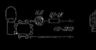
Small 2. Double-sided jointing workbench S2F4-1: 1 - frame, 2 - rear table, 3 - handwheel for the lifting and lowering mechanism, 4 - automatic feeder; 8 – control panel

Small 3. Diagram of a vertical spindle and a warehouse straight line of a double-sided jointing workbench: 1 - unbreakable part of the line, 2 - fixing screw, 3 - bracket, 4 - stand, 5 - wedge-pass gear, 6 - electric motor, 7 - screw for plates and to secure the electric motor, 9 - handle for installing the bracket, 10 - eccentric for installing the hand-held part of the ruler, 11 - the hand-held part of the ruler, 12 - knife head, 13 - spindle
When changing the cutting tool, the automatic feeder is disabled. To galvanize the knife shaft, an electromechanical galmo is transferred, locked behind the “Stop” button of the bench.
The spindle (Fig. 3) is reinforced behind an additional bracket on a non-moving stand. The electric motor is connected to the spindle through a cuneiform transmission. The spindle rotates at a frequency of up to 7000 rpm, the diameter of the cut is 104 mm. The spindle has a rotatable knife head. The warehouse line is straight: the main part is solid, the loose part is moved near the horizontal plane by turning the eccentric. When the handwheel eccentric is turned completely, part of the ruler moves until the unmovable part is 2 mm.
Select robot mode
We first need to determine the thickness of the ball of wood, which is taken away, and depending on the level of ownership of the automatic feeder, then the fluidity of the feed.
The thickness of the ball is known to lie due to the warping of the workpieces, the value of which is determined by trial cutting of 3-5 workpieces.
As soon as the finished workpiece is not planed, the front table is lowered to the required amount. If the thickness of the joint is more than 2-3 mm, jointing should be carried out in two passes.

Small 14. The surface is cut using the milling method: a - beveled look, b - surface with the trajectory of the cut edge of the cutter
Knowing the amount of feed per cutter, the cutting radius, the number of knives and the frequency of wrapping the cutter shaft, it is possible to determine the numerical values of the magnitude of irregularities and the class of roughness of the cut and, for example, for a given class of surface roughness, the permissible value can be determined. smoothness of feeding.
Setting up desktops
Adjustment of one-sided jointing benches involves the installation of the rear and front tables in height, as well as the straight line.
The working surface of the back table must be aligned with the horizontal part of the cylindrical cutting surface or move lower than it by 0.02-0.03 mm. Therefore, kinematic irregularities do not press into the sponge of the table. To place the table in the required position, take a properly cut piece of hard wood, place it firmly on the table and manually rotate the blade shaft. If the bar sticks slightly with the knife, then the table must be inserted correctly, the bar lies on the knife - the table must be raised. Raise the table by moving the nut with a wrench along the screw-thread that connects the eccentric rollers of the back table. Adjust the back table after skin changing the knives and their re-sharpening and jointing directly on the shaft.
The position of the front table and the rear table should be placed on the surface of the wood, which is understood as not necessary to overextend 2 mm. This is indicated by raising the working surface of the front table to a horizontal level, up to a cylindrical cutting stake. The table is moved in height using a handle, inserting it against the supporting floor set on the sector. The design of the table moving mechanism allows the table to be automatically raised and lowered with the hand of the handle, which is corrected during later milling of damaged workpieces.
Having adjusted the tables in height, check the surface between the table jaws and the cutting edges of the knives. There are buti in the range of 2-3 mm. See him with a calibrated uniform garment. The plate can be easily inserted into the gap between the sponge and blade of the knife without play. At a distance of more than 3 mm, the workpiece becomes damaged; if less than 2 mm, the cutting edge of the knife becomes damaged. To adjust the size of the gap, turn the shaft until it does not appear against the jaw. Using screwed screws, move the sled with eccentric rollers until the docks leave a gap of 2-3 mm along the entire cutter shaft, after which the sled is securely secured.
When jointing block workpieces, the position between the straight line and the left end of the cutter shaft must be much larger than the width of the cut workpiece. In the case of dull knives, the ruler is incrementally moved to the right to ensure the fate of the blades of knives that are not dull. The guide line moves across the table by a rack mechanism, which is rotated by a handwheel. For later milling of the edges of the part under the cut to the plate (set to 90°), I install the guide line, bending it with a metal braid or (for a straight cut) with a suitable template. For this purpose, the control pattern (template) is installed on the back table of the bench. The gap between the edge of the template and the surface of the straight line should not exceed 0.05 mm at least 1001 mm. The straight line, inserted under the final cut, is fixed with a screw.
When adjusting double-sided jointing benches, the table and the unbroken part of the straight line (above the back table) should be adjusted in the same way as with single-sided jointing benches. The area of the loose part of the straight edge (above the front table) depends on the thickness of the ball of wood that comes off the edge of the workpiece. They are installed in the required position by turning the eccentric handle, which is adjusted according to the need, so that it takes the form of a dovetail.
If the handle is in the middle of the bend, the ruler will take its position when the thickness of the ball of wood that is tightened is more than 1 mm? If the handle is at 1/4 pitch - 0.5 mm or so. 02 mm. To install the head, press the block with twisted flats to the unbreakable part of the line and rotate the bracket that carries the head, dots, and docks, the knife head does not take position, when the cutting edges of the knives slightly push the block. Fix the positioned head by tightening the locking screw of the bracket.
Both automatic feeders and conveyor devices that feed are set up to supply singing materials. The parts are prepared to feed without “slipping” and with a slight pressure on them from the spring rollers, lances or grooves.
The feed is prepared to remain in place during the refurbishment of automatic feeders. When processing sheets, it is better to install the automatic feeder behind the knife shaft (at a height of 30-40 mm); when processing thick workpieces, the organs to be fed may be located above the front table. The automatic feeder is installed under a small cut to a straight line, which will ensure that the marked workpiece is pressed to it.
Automatic feeders are installed on one-sided jointing benches. To joint the edges of the workpieces, they are installed parallel to the straight line, in which position the automatic feeder presses the workpiece to the straight line and the bench table.
The adjustment is verified by trial jointing. There is no need to exceed 0.15 mm in the area of 1000 mm and in perpendicularity – 0.1 mm in 100 mm.
Work on benches
On a one-sided jointing workbench, one workpiece works, on a double-sided one - two. The layout maker takes the workpiece from the stack, inspects it and places it with the curved surface down on the front table. Pressing the workpiece to the line with both hands, feeds it onto the knives. Further, when moving the workpiece with your left hand, you press the cut part of the workpiece to the flatness of the back table. After the final pass, the layout maker again inspects the workpiece and puts it in a stack, or, if the horns are difficult, sends it again to the layout. Workpieces with a heavily warped surface cannot be planed, so the chips have to be removed in a number of passes and the number of workpieces as a result of such processing changes to the dimensions at which they are used.

Small 5. Device for feeding short workpieces to the cutting tool: 1 - workpiece, 2 - cutter
If a part needs to be aligned with two mutually perpendicular surfaces, then the surface should be aligned (for example, a face), and then press the workpiece with this surface to a straight line and mill the other surface (edge). On a double-sided fugual bench, this operation is completed in one pass.
On a jointing bench it is not possible to mill dimension by thickness or cut workpieces with parallel surfaces. To work on other surfaces, such as planing surfaces, the optimal number of parts that are cut on planing surfaces is 1-1.5 m; Longer workpieces should be milled using a vikorist or a special device (Fig. 5); Most of the time, it is difficult to plan and it is important to do it through a great mass.
If the surface has a curvature or a curve, it is necessary to adjust the position of the tables to the cutter shaft. When “beating” the preparation with knives, moss and scorch appear on the surface, sharpen the knives; If the two narrow planes are not aligned to a straight line, it is necessary to adjust the straight line.
Workpieces short 400 mm, 50 mm and thinner than 30 mm with manual feeding can be directed to the cutting tool only by stitchers, and curved workpieces by templates. On jointing benches, the final milling and cutting of the quarter is blocked.
Construction of workbenches. Planing machines are cut according to the greatest width of the workpiece: 250 mm (SFZ-Z, SFAZ-1, S2FZ-E), 400 mm (SF4-1, SFA4-1, S2F4-1) and 630 mm (SF6-1, SFK6- 1).
For a number of cutting mechanisms, there are one-way or two-way workbenches. On double-sided benchtops (S2FZ-E, S2F4-1), two surfaces of the workpiece are milled simultaneously: the face and the edge.
Depending on the type of supply of the chipped material, there are planing machines with manual and mechanized feed. The feeding is mechanized using attached automatic feeders (SFAZ-1, SFA4-1) or a conveyor feed mechanism (SFK6-1) installed on the machine.
To collect the collected chips and saws, the cutting surfaces are equipped with chip catchers, which are brought to the factory exhaust line.
Single-spindle jointing workbench SF6 indications in Fig. 1. A knife shaft, front and rear tables and a straight line are mounted on a box-shaped machine. The blade shaft is mounted on ball bearings and drives the electric motor through a V-type transmission. The electric motor is mounted on the submotor plate in the middle of the bed. For the splice of the knife shaft there is a galmo, which acts as an electromagnet.

Small 1. Single-spindle jointing workbench SF6: 1 - bed, 2.8 - tables, 3 - fence, 4 - straight line, 5 - knife shaft, 6 - clamps, straight line fastening, 7 - bracket, 9 - scale, 10 - handle adjusting the table at the height
To change the thickness of the ball that is removed, the front table can be moved along the height of the cutter shaft. The back table is designed for precise support of the machined surface of the part. Yogo is unregulated, tobto. We will firmly attach it to the frame, or adjust it in height. Due to the clarity of the control mechanism, it is easier to adjust the bench. The straight ruler is intended for precise barrel basing of the workpiece. It looks like a narrow slab and is mounted on a bracket. They can be placed on the working surface of the table and moved along the width of the bench. The working area of the knife shaft is closed by a fence.
A double-sided jointing machine with horizontal and vertical spindles S2FZ-2 is designed for one-hour milling of the edge of a workpiece. In addition to the one-sided jointing bench, it is additionally provided with a vertical edge jointing head, front and rear straight lines. The front line can be adjusted to fit the head to the thickness of the ball that is removed. The edge-forming head is driven at the wrapper by an individual electric motor mounted on a bracket at the back of the frame. The wrapping material is fed by the wrapping rollers of the automatic feeder.
The jointing workbench is equipped with a conveyor feeding mechanism using the SFK6-1 conveyor. The wine has the appearance of an uncut lance, embellished with little eyes, one of which is driven. Spring metal grips are attached to the lance strips for reliable sealing from the workpiece. The insertion feeding mechanism is on two stands and can move in height from the adjacent electric motor through a screw and worm gear.
Improvement of layouts. Adjustment includes installation of knives at the cutter shaft, adjustment of the position of tables, straight line and feed mechanism. Install the knife shaft after properly preparing the knives. The stench may be sharpened, balanced and equally important. Before installing knives on the knife shaft, you must:
vimknuti entry vimikach; turn the automatic feeder at the idle position or raise the support of the conveyor feeding mechanism; move the line directly to the far right position; lower the front table at the extreme position; secure the blade shaft with a locking device; loosen the screws securing the knives and remove the knives that have become dull; clean the grooves in the body and wedges from chips, saw and resin; Install the prepared knives.
The bottom is installed at the knife shaft so that its cutting edge protrudes beyond the edge of the clamping wedge (chip breaker) by 1.5...2 mm when the thickness of the ball that is cut (chips) is more than 0.2 mm and 0.5...1 mm - with chip thickness less than 0.2 mm. The non-parallelism of the cutting edge of the inserted knife to the working surface of the rear table is no more than 0.1 mm at least 1000 mm.
To achieve the required installation accuracy, use vicoristic control devices (Fig. 2). The accuracy of installation is controlled with a ruler or a wooden block with a cross-section of 30 X 50 mm and a depth of 400 mm. The block is placed on the back table of the bench until the end of the cutter shaft (Fig. 2, a). Rotate the shaft manually and, having loosened the fastening screws, change the position of the knife so that the cutting edge sticks to the block. Tighten the fastening screw closest to the block. When repositioning the block, adjust the position of the other end of the knife. Adjust the position of the knife so that its edge remains consistent with the block throughout. The foot knives can also be adjusted. The screwed knives are still secured with screws. There is no gap between the knives and jaws of the body. The installation position of the knives is controlled by the force of rotation of the knife shaft manually and by the sound that occurs when the knife is connected to the working surface of the template.
In these cases, to achieve precise installation, use a template that looks like a C-like bracket (Fig. 79.6). The bracket provides basic supports with which they are mounted on the body of the cutter shaft. Adjust the template in advance. Use a screw and adjust the base stop to ensure optimal alignment of the knife with respect to the body. When comfortable, bring the cutting edge of the leather knife to the base stop. By moving the bracket along the knife shaft, bring the knives parallel to the shaft housing.
When attached to the indicator (Fig. 2, c), the body is made of precisely polished plates, in which the indicator of the correct type is fastened. Place the attachment on the back table so that the cutting edge of the knife sticks out. The position of the knife near the body is adjusted by adjusting the indicator scale. The device allows you to install knives on one cutting edge with a cut of up to 0.02 mm with one-hour parallelism and the necessary release of knives to the working surface of the back table.
After a residual tightening of the spacer bolts, the knives may be displaced. Therefore, you should once again check the correctness of their installation, rotate the shaft idle and check the reliability of fastening the knives.
The back table is installed so that its working surface is close to the stake, which is outlined by the cutting edges of the knives, or 0.02 ... 0.03 mm below it (Fig. 3, a). If, when the cutting shaft is adjusted, the alignment template (control line) is adjusted, the knives will be installed in the same order. When adjusting the control and setting devices, which are based on the cylindrical surface of the cutter shaft housing, it is necessary to adjust the position of the rear table in height. The steel is adjusted by turning the eccentric rollers through screws 2 with nut 3, and the accuracy of installation is controlled by a corrected template or an indicator device.

Small 2. Alignment of knives at the cutter shaft of the jointing bench: a - with a control line or a wooden block, b - with a template, - with an indicator; 1 - block, 2 - steel, 3 - blade shaft, 4 - stop, 5 - bracket, 6 - lock nut, 7 - screw, 8 - housing, 9 - indicator
When cutting block parts, straighten the straight edge so that it reaches the left end of the cutter shaft a little more than the width of the cut workpiece. When the knives become dull, move the ruler to the right and trim the parts with parts of the knife shaft that are not yet dull. When processing parts with non-perpendicular surfaces, straighten the ruler so that the cut between the working surface and the knife shaft is dull.
The straight lines of the double-sided jointing bench perform the same functions as the front and rear tables. Adjust the rulers around the edge jointing head with the handle, and set the size of the ball to be adjusted behind the scale mounted on the stand.
The automatic feeder or the conveyor feed mechanism is adjusted in height (Fig. 3, b) with a handwheel in the amount of workpieces that are being cut. Stand on the working surface of the front table up to the rollers (conveyor fingers) that are fed, due to the thickness of the workpiece being 2...3 mm less. The automatic feeder is positioned above the cutter shaft so that the first roller that feeds is located above the front table at a distance of 50...60 mm from the cutter shaft, and the other rollers are above the rear table.
Along the straight line, the autofeeder is oriented so that the rollers are not parallel to the axis of the cutter shaft (cut 1...30), for which the autofeeder is deployed along the vertical axis. This kind of rotation of the rollers that are fed allows you to press the workpiece to a straight line and paints the base.
The pressure of the elements that are served on the preparation must be sufficient for serving without licking. The overwhelming pressure is caused by the increased wear of the automatic feeder mechanisms and the deformation of the part in the area of the cutter shaft.

Small 3. Adjustment of the jointing workbench: a - adjustment of the tables; b - installation of an automatic feeder; 1 - rear table, 2 - screw rods, 3 - nut, 4 - blade shaft, 5 - front table, 6 - handle for adjusting the ball that is removed, 7 - scale, 8 - eccentric roller, 9 - rods
The front table is installed so that its working surface is lower than the upper hardening stake, which is described by the cutting edges of the knives. The amount of protrusion of the knives to the front table indicates the size of the ball, which is removed. Since the largest ball needs to lie at the stage of processing the workpiece, the table is adjusted in height before cutting the skin workpiece. Wrap the eccentric rollers through the rods and use handle 6 to raise or lower the table. I can control the value on the scale.
Work on benches. A manually fed jointing bench for processing small-sized workpieces is serviced by one worker. I prepare the benchtop from the stack, visually evaluate the round and curved edge of the workpiece, and place it with the curved surface on the front table. Severely warped and defective workpieces should be rejected
Pressing the workpiece to the table and straight line with your left hand, feed it onto the knife shaft with your right hand. When russian, the front end of the workpiece is blown into the withered fence and in this way access to the knives that are being wrapped is ensured.
After cutting the front end of the workpiece, use your left hand to firmly press the cut piece to the flatness of the back table and continue feeding.
When feeding, it is important to follow the position of your hands so that they are aligned with the knife shaft and place them on a safe stand. When processing other parts, there is a risk of injury, so workpieces shorter than 400, as long as 50 and thinner than 30 mm must be processed using a special cutter (Fig. 81). After the skin pass, the tester evaluates the softness of the cutting and whether the surface is not cut again or not.
If a part needs to be leveled on two surfaces, the surface is milled, and then the edge, pressing the part with the previously trimmed surface to the guide line. On double-sided workbenches, operations are completed in one pass.
When processing massive and large-sized parts, the bench must be operated by two workers. The bench worker bases and feeds the workpiece, and another worker, standing behind the bench, helps at the final stage of processing, receives the finished part and puts it in a stack. If necessary, additional roller tables are installed in front and behind the bench.
The fluidity of manual feed on the bench is selected individually for the leather workpiece in the form of defects and the required depth of milling. When cutting and milling against the fibers, the fluidity of the track is reduced. The depth of milling should be within the allowance for machining and the size of defects.

Small 4. Scheme of cutting other parts using the help of a shtovhach
A careful allowance in one pass does not allow you to eliminate the necessary processing thickness. The best effect is achieved in two or more passes with a small milling depth, since in this case the deformation of the part changes under the pressure forces and internal stresses of the workpiece material.
For benchtops with mechanized feed, the feed speed is selected according to the schedule in order to maximize the impact of the electric motor on cutting and ensuring the specified surface roughness.
The removed parts must be checked for accuracy of processing. Applying the chipped surfaces one part to another, visually judge the amount of chipping based on the amount of clearance between them. In addition, the flatness of the finished surface can be checked using a straight line and a feeler gauge. There is no need to exceed 0.15 mm on the surface by up to 1000 mm. The adjacent surface structures are mutually perpendicular. It is permissible to set the margin to 0.1 mm at a height of 100 mm. Perpendicularity is checked with a checking braid and feeler gauge. The roughness of the chipped surface ranges from 60...100 microns. If the details do not correspond to the intended results, a trace of benefit will be found.
The jointing workbench SF6-2 is folded from a stand and a work table, which has two horizontal smooth chavun plates (back and front), secured with thin steel jaws on the side of the cutter shaft. The purpose of the sponges is to protect the ends of the slabs from washing, change the gap between the knives and slabs, and create a support for the fibers when cutting chips. A knife shaft is placed between the plates. The knife shaft is rotated so that the cutting edges of the knives mounted on the new ones are on the same level as the back plate. The skin plate can be raised and lowered with the help of a screw.

Small 1. Device for balancing knife shafts
A straight ruler is attached to the table so that it can be adjusted to fit the width of the table. The jointing workbench directly drives the electric motor through a wedge-pass transmission.
When planing, place the material that is being formed on the front plate of the table, as far as possible, with a straight cut to the cutter shaft and, pressing firmly to the plate with your left hand near the knives, with your right hand far from them, push it onto the knife as you plan on the bottom surface of the part.

Small 2. Planing workbench SF6-2:
a - front view: 1 - electric motor, 2 - back plate of the work table, 3 - straight line, 4 - handle for adjusting the height of the front plate, 5 - knife shaft, 6 - fly fence, 7 - front plate of the work table, 8 - starting device 9 - bed; b - jointing diagram: 1 - rear plate, 2 - front plate, 3 - volume of chips that are removed.
When the front end of the part passes behind the knives, take the part with your left hand to the surface of the back plate, and with your right hand to the surface of the front plate. The pressure is as smooth as possible, and the delivery is smooth and even.
The edge is touched on the wide side of the part (face), and then on the narrow side (edge). When planing the other side of the bag, press the part to the table and to a straight line.
To remove any curls from scuffing the fibers, you need to plan on the ball. When planing parts from pine wood, it is recommended to wipe the work table with a plaster moistened with gas, as the resin that can be seen from the wood sticks to the table and makes it easier to dry the parts.
When carefully installing the knives on the knife shaft, it is still not possible to move their cutting edges exactly one stake at a time, and there is a difference of 0.5-0.1 mm in the cutting radii. Through this, quills appear on the chipped surface. To change its difference, install a jointer for jointing and straightening knives at the installation site. The device is released simultaneously with the hinged versat and the attached one. After planing and straightening the knives, the difference between the cutting radii changes to 0.03-0.02 mm and the planed surface becomes more smooth.
Place the sharpening part in contact with the blade of one knife on the knife shaft and secure it in this position. Then turn on the pressure and move it straight along the entire length of the knife, tightening the blade and straightening it. Having finished dressing one knife, rotate the knife shaft, bring the other knife under the sharpening part and repeat the shaping and straightening. This method is used to trim the blades of all knives attached to the cutter shaft.
To feed the material, it is necessary to use special cutting blocks to ensure the safety of the work and prevent fingers from touching the knives.
The width of the planing on the SF6-2 bench is 600 mm, the thickness of the ball is 6 mm, the cutting diameter is 125 mm, the number of knives on the shaft, the number of wraps of the blade shaft is 5000, the tension of the electric motor on the blade shaft is 4.5 kt. Verstat weight 860 kg.
Planing bench SF4-4 is used for planing and shaping the surface along the plane and for milling boards and bars into cut pieces. On the bench there is a round double-knife shaft with wedge-shaped knife fastenings. The spindle for vertical milling is folded from the front and rear straight lines and the spindle block with a double blade head. The front rolling line must be moved accordingly to the specified milling depth; the rear line is firmly secured. The spindle collapses due to an individual electric motor driven by V-belts. The workstat is equipped with an automatic feeder UPA-3, which automatically feeds the marked parts.
Planing width on the bench 400 mm, thickness of the ball, which is removed 6 mm, diameter of the cutter shaft 125 mm, cutting diameter 128 mm, number of knives on the shaft, thickness of the electric motor of the cutter shaft 2.8 kt, thickness wraps of the knife shaft for khvilina 5000, vaga verstata 620 kg.
The SF4-4 jointing workbench allows for jointing and milling, so that on one workbench you can carry out a number of operations that require two different workbench. There is a saving in production space, and the installation productivity is improving. Productivity will increase twice as quickly as the number of workers increases.

Small 3. Planing workbench SF4-4
To prevent accidents from occurring, install a dry shield or a curtain over the blade shaft, so that during work, the part being processed is inserted into the container, and after the part passes under the spring, the entire blade is closed again shaft
To mechanize the supply of workpieces, you can install attached roller automatic feeders, in which the rollers are wrapped around an electric motor through a gearbox. The body of the automatic feeder, with the help of important elements and a stand, can be installed so that the rollers press the workpiece that is being cut to the table or to a straight line.
Basic fences for woodworking machines are, for the most part, bulky and do not compromise their versatility. The Kurgan Woodworking Workstation Plant produces the UPA-3 automatic feeder, which can be used as a universal fence on circular saw, planer and milling workbenches.
When adjusted with a UPA automatic feeder, the stand with anchors is installed either on the benchtop table, or on the reinforced handrail from the benchtop, as well as on the adjacent foundation, right-handed or on the benchtop.

Small 4. Dry fences to the surface planer:
a-shield of Erokhin; b - viyalovo fence; 1 - spring shield; 2 - curtain; - automatic feeder with top clamp: 1 - stand, 2 - automatic feeder, 3 - front table
The body of the automatic feeder can be installed behind additional hinges and stands so that the rollers press the workpiece to the table or to a straight line.
On the jointing bench, the UPA-3 automatic feeder is installed so that the first pair of rollers is located above the front part of the table, and the third pair is positioned above the back. Along the width of the workbench, the rollers that feed are installed in the middle of the planed material.

Small 5. Universal fence - automatic feeder UPA-3 (side view of the material that is being formed)
Between the rollers and the workbench table, less material is installed to be fed. The material is fed manually to another pair of rollers, and then by an automatic feeder.
Double-sided jointing workbench S2F-4 with mechanical feed and edge jointing head, indications in Fig. 6. The workbench is set up for one-hour planing and jointing of the bottom layer and the right edge of one workpiece (planing to the end). The workbench is folded from a chavun frame, on which two plates are moved on eccentric supports - front and rear, between them there is a knife shaft with a diameter of 125 and a depth of 410 mm, which forms a fence. The cutter shaft is wrapped on ball bearings and driven by a 4.5 kW electric motor through a wedge drive gear. There is a straight line on the slabs. The front plate serves directly for workpieces before planing, and the rear plate is intended for moving workpieces during planing. The size of the ball of wood that is removed is adjusted by lifting or lowering the front table using the additional handle, which is the height indicator. The rear plate is adjusted using a screw or nut. The planing width of the workbench is 400 mm. The thickness of the cut workpiece is 15-100 mm, the thickness of the ball is 6 mm, the number of knives on the shaft is 2-4, the number of wraps per blade of the cutter shaft is 6000, the weight of the workbench is 800 kg. On the workbench, in addition to the horizontal knife shaft, a vertical knife head is mounted, which helps to plan the edge of the workpiece. The vertical knife head is mounted on an edge jointer spindle mounted on a special support. The automatic feeder and edging head are powered by individual electric motors. Therefore, the spindle drive of the vertical cutter head is driven by one electric motor with a tension of 1.7 kW through a V-belt gear. The blanks and lumber are fed to the horizontal cutter shaft via an additional automatic feeder, which is driven by another electric motor through a gear box. The automatic feeder is located on the side of the workbench on a vertical rod and is stored so that the prepared workpieces can be transferred in vertical and transverse directions. Button control.

Small 6. Double-sided jointing workbench S2F-4 with automatic feeder and edge jointing head:
1 - control buttons, 2 - vertical fence of the knife shaft, 3 - rear table, 4 - automatic feeder, 5 - edge jointer spindle, 6 - screw for height adjustment of the rear table, 7 - straight line, 8 - eccentric mechanism handle adjusting the front 9 - front table
Planing machines with mechanical feed of parts are more productive, while the lower ones are those with manual feed.
The device for the mechanized feeding of parts contains rollers coated with gum or a conveyor belt. The rollers are wrapped around an electric motor through a gearbox. The conveyor lance has spring fingers. The endless lances of fingers, shifting around the side of the knife, begin to squelch the workpiece and stick them over the knife shaft of the workbench. Depending on the number of parts being washed, the conveyor lanyard can be installed at different heights. The lantsug is driven by an individual electric motor with a tension of 0.6 kW.
The jointing workbench SF6A-2 with a conveyor feed is thick and can be used for processing one or several workpieces with a width of up to 600 mm. The blade shaft of the machine is driven into the Roc through a belt transmission by an electric motor. For quick galvanization of the knife shaft, use an electromagnetic galmo, which is placed on the end surface of the disk mounted on the end of the shaft. Along the disc, open the stopper, which fixes the position of the shaft when sharpening the knives. The material is supplied by a double-chain conveyor secured with transverse slats, which have spring grooves. Due to the large number of pasurs, the pressure on the skin on the workpiece is insignificant, and the workpiece does not become deformed as it rolls across the table. Lancets with straps are tensioned on two pairs of eyes - one driven and the other tensioned. To sharpen and joint the knives directly on a bench or a special device.

Small 7. Planing bench and attachment for mechanical supply of parts:
a – hidden view of the verstat; b - diagram of the conveyor mechanism on the jointing bench: 1 - knife shaft, 2 - workpiece cut, 3 - back plate, 4 - pressure fingers, 5 - conveyor lance, 6 front plate

Small 8. Kinematic diagram of a jointing bench with a conveyor feed:
1 - mechanism for adjusting the height of the rear table; 2 - rear table; 3 - conveyor drive mechanism; 4 - conveyor; 5 - front table; 6 - mechanism for adjusting the height of the front table; - knife shaft
The working diagram of the jointing workbench is shown in Fig. 9. The details that are processed on the workbench should be laid out on the workbench so that the worker does not have to work on difficult transitions and flows.
On the work table, where there is a gap in the cutter shaft, a sharp steel plate must be installed, secured flush to the surface of the table. Stand between the edges of the pads and the surface that describes the blades of the knives, no more than 3 mm.
The knife shaft is equipped with a sliding device for fastening the knives.

Small 9. Diagram of the working area of the jointing bench:
1 - layout maker’s place; 2 - blanks; 3 - planed parts.
For workpieces as short as 400 mm, as short as 50 mm or as thin as 30 mm, when feeding by hand, it is necessary to plan the parts using special blocks - cutters. Planing of thin and short parts in batches can only be carried out using cured tsulagi. Shaped, curved planing is protected.
After installing both halves of the table at the required height, the lifting mechanism must be securely secured to its position. The area of the back table is equal to the cylindrical surface, which is described by the blades of the knives.
The non-working part of the knife shaft must be closed with a fence that automatically moves with a straight line. The fastening of the straight line with clamps is blocked.
On jointing benches with mechanical feed, the simultaneous planing of two or more different parts is allowed unless the skin is firmly pressed against them.
The planing workbench Logosol DH410 is primarily purchased by those who need a workbench for the processing efficiency of a multi-sided planer, but they also assume that it takes a little more than an hour to process the saw blades. The main advantage of the DH-410 compared to the PH-260 lies in the fact that you have an inexpensive, reliable planing workbench with a spindle width of 410 mm.
Demonstration of PH-260/DH-410 robot:
DH-410 can also be used as a vertical workbench with a mechanism that feeds. If you do not need to plan the side sides of the boards, replace the steel rollers with gum.
The double-sided workbench Logosol DH410 is designed for cutting workpieces with a width of 410 mm and a thickness of 260 mm. There are enough viruses. For profile planing, profiling and planing can be done in one hour. On the left side of the machine there is a side cutter that planes or mills the side sides of workpieces. To achieve multi-sided profiling or thicknessing, the workpiece is planed in two. The maximum dimensions for double-sided profiling are 310 mm width and 100 mm thickness. The workbench can produce everything from timber for cutting to thin profile slats. By increasing the width of the cast frame, you can produce thin blanks such as lining and cladding. The difference in the depth of burial between the cutter knives is every thousandth of a millimeter, which is why the surface of the end product comes out extremely smooth and even.
For the craftsman there is a wide selection of profile knives for molding. If necessary, knives can be manufactured in a special configuration. Verstat can be planed into deep, sided shapes. Verstat has the ability to correct cutting cuts because The upper horizontal cutter can plan to a depth of 8 mm in one pass, and the beam cutter can plan even deeper.
The standard configuration of the planing bench is equipped with flat knives for thicknessing HSS for the upper horizontal cutter of 50 mm. for side cutter. All knives are made from standard steel. The spindle diameter of barrel cutters is 30 mm, which allows you to select cutters from existing ones.
| Workpiece size for one-sided planing, mm | 410 x 260 |
| Workpiece size for double-sided planing, mm | 410 x 260 |
| Dimensions of horizontal cutter, mm | D=72, L=410 |
| Max. diameter of horizontal cutter, mm | D=72, L=410 |
| Pressure e/d, kW | 2x3 kW. |
| Number of revolutions, rpm | 6000 |
| Glibin planed with a horizontal cutter, mm | up to 8 |
| Depth of profiled horizontal cutter, mm | to 10 |
| Vertical cutter size, mm | D=90, H=40 |
| Depth of profiled vertical milling cutter, mm | up to 30 |
| Max. Diameter, mm | 140 |
| Planting diameter of cutters, mm | Dosi = 30 |
| Horizontal knives, mm | 2 x 410 |
| Cannon knives, mm | 2 x 50 |
| Power supply pressure, kW. | 0,18 |
| Standard feed speed, m/hv. | 6 |
| Additional feed speed, m/h. (Option 1) | 2-12 |
| Additional feed speed, m/h. (Option 2) | 4-24 |
Positive features of the verstat:
Lita bed

Possibility of simultaneous activation of the skin using three engines.

6000 revolutions per blade guarantee a smooth surface.


Maximum dimensions of the surface to be cut: 410x260 mm.

Stainless steel for the vikoristan position of the premises.
With a low coefficient of insertion, rubbing on the bench table guarantees a smooth feeding.
Requires minimal maintenance.
Brochure for the multi-sided workbench PH-260 download (*pdf, 0.85 Mb)
A guide to the operation of the double-sided workbench PH-260 download (*pdf, 1.03 Mb)
Catalog of planing knives download (*.pdf, 3.96 Mb)
The catalog of planing knives can be equipped with butts for profiles of moldings, which can be removed during their curing. Planing knives can be used either in the form of straightening knives or in the form of profiling knives. Swedish knives are made from high oxide steel and one sharpening of the knives sharpens 300-600 m.p. material. Sharpening power – 5-10 times.