This type of stabilizer is best for home use. Types of stabilization and their priming
In order to cope with changes in the margins, struma stabilizers are necessary. These devices can be differentiated by their characteristics, and are connected with their life requirements. However, the installations in the booth are not very effective in terms of stabilizing the flow; otherwise, the vibrancy will require a stable voltage. Thanks to these models, they now have the ability to extract reliable information from their investigations.
What is a moisture stabilizer?
The main element of the stabilizer is the transformer. If you look at a simple model, there is a direct place. It is connected to capacitors, as well as resistors. In Lancusia, stinks can be installed in different types and the boundary support of the stink can be seen differently. The stabilizer also has a capacitor.
Robot principle
If the transformer consumes the current, its cutoff frequency changes. At the input this parameter is around 50 Hz. Once the stream is changed, the limiting frequency at the output becomes 30 Hz. High-voltage rectifiers therefore evaluate the polarity of the voltage. The stabilization of the flow is often due to capacitors. Reduced transcode is observed in resistors. At the output, the voltage again becomes constant, and the transformer operates with a frequency of no more than 30 Hz.
Principle diagram of a relay device
The relay stabilizer (diagram shown below) includes compensation capacitors. Bridges straighten at times vikorystvuyutsya on the cob of lantsug. Also note that there are two pairs of transistors in the stabilizers. One of them is installed in front of the capacitor. This is necessary to increase the cutoff frequency. In this case, the steady-state voltage will be at around 5 A. In order for the nominal support to be vitrified, the resistors will be victorious. For the simplest models there are power two-channel elements. The transformation process sometimes takes a long time, and the dispersion coefficient will be insignificant.
Attachment to the triac stabilizer LM317
As is obvious from the name, the main element of LM317 (stream stabilizer) is a triac. This gives the device a colossal increase at the boundary stress. At the output, this indicator fluctuates around 12 V. The external support of the system is seen at 3 Ohms. For a high smoothing coefficient, multi-channel capacitors are used. For high-voltage devices, transistors of the open type are used. The change in their position in such a situation is controlled by the change in the nominal output stream.
The differential support LM317 (strum stabilizer) vibrates 5 Ohms. For dimming devices, this indicator may become 6 ohms. The undisturbed mode of the throttle flow is ensured by a tightened transformer. It is installed in the standard circuit behind the straightener. Diode bridges for low-frequency devices are rarely used. If you look at devices at 12, then for them the power resistors are of the ballast type. This is necessary in order to reduce the level of Lanzug.
High frequency models
The high-frequency stabilizer on the transistor KK20 is disrupted by a rapid conversion process. It is necessary to change the polarity at the output. Frequency-setting capacitors are installed in the lamps in pairs. The pulse front in such a situation should not exceed 2 μs. Otherwise, the stream stabilizer on the KK20 transistor is sensitive to significant dynamic losses. The number of resistors in the Lancus can be obtained with the help of boosters. In the standard scheme, at least three units are transferred. To change heat losses, use umbilical capacitors. The specific characteristics of the switch transistor depend only on the size of the dilator.

Pulse width stabilizers
The pulse-width stabilizer is modified by high values of the inductance of the choke. It is charged for the exchange rate of the debtor. Also ensure that the resistors in this circuit are dual-channel. Strum the stench of the building is let through in different directions. The capacitors in the system are vicorized. Behind the frame of which the boundary support at the output is visible at approximately 4 ohms. The maximum requirement for stabilizers is 3 A.
For virtual devices, such models are rarely used. In this case, the voltage is limited to no more than 5 V. Thus, the coefficient of dissipation is within the normal range. The high characteristics of the switch transistor in stabilizers of this type are not very high. This is due to the low number of resistors to block the flow from the rectifier. As a result, high-amplitude faults lead to significant heat losses. Pulse drops are sometimes eliminated by reducing the neutralization of transformer power.
The conversion process is handled by the ballast resistor, which is located behind the rectifying bridge. Conductor diodes in stabilizers rarely vibrate. The need for these falls due to the fact that the front of the pulses at Lanzug, therefore, is selected at 1 μs. Through war, dynamic losses in transistors are fatal.
Diagram of resonant devices
The resonant stabilizer struma (the diagram is shown below) includes low-capacity capacitors and resistors with different supports. Transformers are an unknown part of the power supply. To increase the coefficient of korisnoi action, vikorista is used without treatment. The dynamic characteristics of resistors increase as a result. Low-frequency transistors are mounted directly behind the rectifiers. For good conductivity of the current, the original capacitors operate at different frequencies.

Stabilizer for grinding fluid
A stabilizer of this type has an invisible part that is designed for voltage up to 15 V. The external support of the devices is compressed up to 4 Ohms. The voltage of the exchanger at the input to the middle becomes 13 V. In this case, the smoothing coefficient is controlled by the type of closed capacitors. The amount of pulsation at the output lies in the resistor circuits. The threshold voltage of the struma stabilizer can be set to 5 A.
In this case, the differential support parameter is set to the 5 Ohm value. The maximum permissible power of the switch is 2 W. It is important to note that the stabilizers of the exchangeable stream suffer from the same problems with the pulse front. Change their rocking in every building or bridge straighteners. In this case, the size of the debt is strictly guaranteed. To reduce heat losses, stabilizers are equipped with heaters.

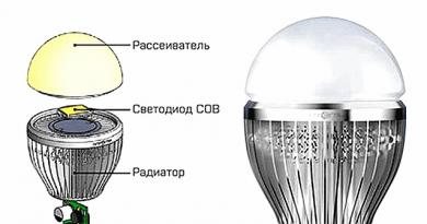
Model for LEDs
To regulate the light-emitting diodes with great intensity, the stabilizer is not needed. In this situation, the goal is to reduce the risk of dispersion as much as possible. You can create a stabilizer for light-emitting diodes in several ways. In the meantime, the models will have to change their minds. As a result, the limiting frequency in all stages is selected at 4 Hz. In this case, this results in a significant increase in the productivity of the stabilizer.
Another method is found in the use of vicoristic supporting elements. In such a situation, everything depends on the neutralization of the alternating stream. To reduce dynamic losses, the transistors in the circuit are switched to high voltage. Open the open type capacitors from the hard pressed elements. For the highest speed of transformers, switching resistors are used. In the circuit, the stench is usually displayed behind the straightening bridge.

Stabilizer with regulator
Regulatory stabilizer to meet the demands of the industrial sector. With this additional help, the koristuvach can carry out the cleaning of the annex. There are a lot of additional models that are insured at a distance. For this purpose, controllers are installed in the stabilizers. The limiting voltage of the alternating current of such devices is generated at least 12 V. The stabilization parameter at the same time becomes less than 14 W.
The indicator of the boundary voltage lies inclusive of the frequency of the device. To change the coefficient of smoothing regulation, the stabilizer uses vicoristic emnesis capacitors. The maximum flow of the system is supported at around 4 A. However, the differential support indicator is allowed at around 6 Ohms. All we can say about the good productivity of stabilizers. However, the difficulty of dissolving may become even more severe. It is also important to know that the non-disruptive throttle mode is ensured by the transformer frame.
Voltage is supplied to the primary winding through the cathode. The blocking of the stream at the output is stored in excess of the capacitors. To stabilize the process, the defenders are asked not to fight. The system's speed is ensured using additional pulse drops. The rapid process of re-creation of the stream in the lancius leads to a decrease in the front. The transistors in the circuit are of the on/off switch type.

Stabilizers for standing fluid
The stationary flow stabilizer operates on the principle of continuous integration. Transformations for all models indicate this process. To enhance the dynamic characteristics of stabilizers, dual-channel transistors are used. To minimize heat losses, the capacitance of the capacitors is important. The exact design of the value allows you to create a straightening display. With a steady-state output voltage of 12 A, the maximum limit value may become 5 V. In this situation, the operating frequency of the device is maintained at 30 Hz.
The threshold voltage is due to the blocking of the transformer signal. The pulse front is not liable to exceed 2 µs. The voltage of the switching transistors is restored only after reversing the circuit. Diodes in this circuit can be used in addition to the conductor type. Ballast resistors reduce the stabilizer flow to significant thermal losses. As a result, the dispersion coefficient has increased even further. As a result, the amplitude of the vibration will increase, and the inductive process will not occur.
Parametric voltage stabilizer- devices in which the stabilization of the output voltage is due to the strong nonlinearity of the current-voltage characteristics of the electronic components that are used to drive the stabilizer (the same as for the internal power electronic components without requiring a special voltage regulation system).
To create parametric voltage stabilizers, use zener diodes, stabilizers and transistors.
Due to their low CCD, such stabilizers operate mainly in low-current circuits (up to several tens of milliamperes). Most often, the smell is caused by the reference voltage (for example, in circuits of compensating voltage stabilizers).
Parametric voltage stabilizers come in single-stage, multiple-stage and bridge types.
Let's take a look at the simplest parametric voltage stabilizer based on a zener diode (the diagram is shown below):
- Ist - flow through the zener diode
- In - strum navantazhenya
- Uwih = Ust - output stabilized voltage
- Uvkh - input voltage is unstabilized
- R 0 - ballast (intermediate, extinguish) resistor
The operation of the stabilizer is based on the power of the zener diode, so that at the operating range of the current-voltage characteristic (from Ist min to Ist max), the voltage on the zener diode practically does not change (in fact, it changes significantly Ust min to Ust max, but you can also use Ust min = Ust max = Ust).
In the induction circuit, when changing the input voltage or the voltage source, the voltage on the voltage practically does not change (it is not the same as on the zener diode), instead the source through the zener diode changes (at the same time and change the input voltage and flow through the ballast resistor (the same). Then, the excess input voltage is extinguished by a ballast resistor, the value of the voltage drop across which resistor lies in the stream through the new one, and the voltage through the same lies in the same as the stream through the zener diode, and in this way, it comes out when changing the stream through the stabilizer The electrode regulates the voltage drop across ballast resistor.
Rivnyanna, what to describe the work of this scheme:
Uin = Ust + IR 0, doctor, so I = Ist + In, can be rejected
Uin = Ust + (In + Ist) R 0 (1)
For normal operation of the stabilizer (the voltage on the voltage must always be in the range from Ust min to Ust max) it is necessary that the flow through the zener diode always be in the range from Ist min to Ist max. The minimum flow through the zener diode will flow at a minimum input voltage and maximum flow. I know, we know ballast resistor reference:
R 0 =(Uin min-Ust min)/(In max+Ist min) (2)
The maximum flow through the zener diode will flow at a minimum current and maximum input voltage. The doctor said that rather than a minimal flow through the zener diode, using the equation (1) you can find out the area of normal operation of the stabilizer:
Having regrouped this line, we can remove:
Otherwise:
If you take into account that the minimum and maximum stabilization voltage (Ust min and Ust max) vary slightly, then the first addition on the right side can be set equal to zero, then level, which describes the area of normal operation of the stabilizer, in the near future I see:
This formula clearly shows one of the shortcomings of such a parametric stabilizer - we cannot greatly change the voltage flow, as long as there is a range of input voltage of the circuit, moreover, it is possible to increase the range The zones for changing the current flow cannot be larger, the lower range for changing the flow of zener diode stabilization (the fragments are right; part of the relationship is becoming negative)
Whether the flow of interest is constant or changes slightly, Then the formula for the designated area of normal work becomes even more elementary:
Next, let’s analyze the CCD of our parametric stabilizer. This is determined by the pressure settings that are achieved at the entrance to the input pressure: KKD=Ust*In/Uin*I. If you believe that I = In + Ist, then we reject:
From the remaining formula it is clear that the greater the difference between the input and output voltage, as well as the greater the flow through the zener diode, the stronger the CCD.
In order to understand what “harder” means and how bad the situation with the CCD of this stabilizer is, let’s use the same formulas to try to figure out what would, if anything, reduce the voltage, say 6-10 Volts up to 5. Let's take a very basic zener diode, say KS147A. Stabilization levels can vary between 3 and 53 mA. In order to take away the area of normal operation at 4 Volts with such parameters of the zener diode, we need to take an 80 Ohm ballast resistor (according to formula 4, so that our current flow is constant, but if this is not the case, then everything will be even worse). Now, using formula 2, you can understand what is the most important thing in life. The output is only 19.5 mA, and the CCD at this level will be in the range of the input voltage in the range from 14% to 61%.
In order to determine what maximum output stream we can take into account that the output stream is not constant, but can change from zero to Imax, then if the level systems (2) and (3) have been completely vibrated, R is rejected. 0 =110 Ohm, Imax = 13.5 mA. As you can see, the maximum output current is 4 times less than the maximum output of the zener diode.
Moreover, the output voltage is detected on such a stabilizer, therefore the instability is due to the output stream (in the KS147A at the operating point the voltage changes from 4.23 to 5.16 V), so You may appear unpleasant. The only way to combat instability in this phase is to take a larger working section of the VAC - one in which the voltage changes not from 4.23 to 5.16 V, but, say, from 4.5 to 4.9 V, and in this case Ipadku i working strum the zener diode will no longer be 3..53mA, but, say, 17..40mA. Apparently, since the area of normal operation of the stabilizer is so small, it will become even smaller.
However, the only advantage of such a stabilizer is its simplicity, because, as I have already said, such stabilizers generally exist and tend to be actively used as a source of reference voltage for more complex circuits.
The simplest scheme that allows you to remove a significantly larger output stream (or a significantly wider area of normal operation, or something else) - .
Lecture 8
Voltage and flow stabilizers.
Principle of stabilization Types of stabilizers.
The magnitude of the voltage at the output of the rectifiers, used for the operation of various RTUs, can fluctuate at significant intervals, which affects the operation of the equipment. The main reasons for this vibration are changes in voltage at the input of the rectifier and changes in voltage. At the limits of the alternating current, beware of voltage changes of two types: large ones, which last for several minutes to several years, and short ones, which last for several seconds. Like other changes, the robotic equipment is negatively affected. For example, TWTs cannot operate without voltage stabilization. To ensure the specified accuracy of measuring devices (electronic voltmeters, oscillographs, etc.), voltage stabilization is also required.
Voltage stabilizer
is called a device that maintains the tension on the vantage with the necessary precision when changing the support of the vantage and the tension at the edges.
Stabilizer struma
It is called a device that supports the tension line with the necessary precision when changing the tension support and tension at the leading edges.
The stabilizer, in addition to its main functions, provides pulsation suppression.
The work capacity of the stabilizer is assessed by the stabilization coefficient, which is the current ratio of the voltage change at the input to the voltage change at the output of the stabilizer:
The level of stabilization is also assessed by the apparent instability of the output voltage.
Internal support
![]() (3)
(3)
Pulsation smoothing coefficient
![]() (4)
(4)
where Uin~, Uout~ are the pulsation amplitudes of the input and output voltage. The following parameters are important for strum stabilizers:
Stabilization coefficient of the stream behind the input voltage
![]() (5)
(5)
Stabilization coefficient when changing the vantage support
![]() (6)
(6)
The coefficient of action is determined for all types of stabilizers based on the input and output of active pressures
There are two main methods of stabilization: parametric
і compensatory
.
Parametric a method of basing on vicoristan nonlinear elements, the structures of which are intended to redistribute the flow and voltage between adjacent elements of the circuit, leading to stabilization.
The block diagram of a parametric stabilizer consists of two elements - linear and nonlinear.


When changing the voltage at the input of the stabilizer in wide ranges (), the voltage at the output changes in significantly smaller ranges ()
Parametric voltage stabilizers will be based on silicon stabilizers. An avalanche breakdown of the p-n junction develops in a silicon zener diode at a low setting (div. Figure (a)). Make the working fork appear behind a different alignment of the axes (marvelous little ones (b)). The working plot is bounded by the maximum permissible thermal regime Imax.


In a parametric variable voltage stabilizer, the linear element is a capacitor, and the nonlinear element is a pressure reactor.
Compensatory
The stabilizer is exposed to the presence of a negative feedback loop, due to which the signal of inconvenience is strengthened and flows into the regulatory element, changing its support, leading to stabilization. Compensating stabilizers, in which the transistor is constantly (constantly) in an open state, are called linear or continuous regulation. In a pulse regulation stabilizer, the transistor operates in the switching mode.
Normal operation of electronic equipment is possible by maintaining voltage within specified acceptable limits. For example, for the life of vibrating devices that operate with an accuracy of 0.1%, the required stability of the life voltage is 0.01%. Most rectifiers do not provide the specified voltage stability. A change in the live voltage can occur through a change in voltage in the alternating current or a change in the steady current in the equipment. By changing the drive support, the flow and the voltage drop on the internal support of the direct devices are changed, which leads to a change in the life voltage.
To maintain the voltage within the permissible range between the filter and voltage, a device called a voltage stabilizer is turned on. The voltage stabilizer maintains the voltage of the equipment with a given accuracy when changing the voltage support and the voltage of the boundary at specified intervals. After the stabilizer, the protection device is turned on due to the reversal of the stabilizer.
Parametric constant voltage stabilizers
As nonlinear elements, cream or gas-discharge zener diodes are embedded in them (Figure 5).
Figure 5 – Principle diagram of a parametric voltage stabilizer
Since, with the use of silicon zener diodes, the part of the gate of the current-voltage characteristic is changed, then the zener diode is switched on by the anode to minus, and by the cathode to plus input voltage. The resistance of the resistor to be extinguished, R G and the direction of R N are selected in such a way that the flow in the lance I in = I st.
With an increased (changed) input voltage U input to the zener diode  I st increases (changes) at the intervals from I st minimum to I st maximum, and the strum I n becomes permanent. This will ensure the stability of the voltage on the vantage.
Parametric zener voltages are simple and reliable, but there may be some shortcomings:
Small coefficient of stabilization, small coefficient of cortical action, low tension, inability to regulate output voltage, work well on constant pressure.
Compensatory voltage stabilizers
The principle of voltage stabilization can be seen from the example diagram (Figure 6). The circuit consists of a regulatory element P, a vibrating element U(PV) and an operator (U). When changing the voltage U in or the flow of voltage I at the specified boundaries of the output voltage U may become unchanged. This is consistent with Kirchhoff’s law U out = U in -U p = const. To maintain the output voltage constant, the operator must change the position of the variable resistor motor to match the voltmeter reading.
Figure 6 – The principle of the voltage stabilizer
The diagram (Figure 6) is suitable for large changes U in and I out. In real devices, U input and n can be changed in pulse mode or with great speed. Therefore, stabilizers can be prepared using elements made from high-speed liquid code. with a variety of transistors and microcircuits.
Stabilizers can be combined with sequential (Figure 7 a) and parallel (Figure 7 b) inclusions of the control element to ensure proper implementation.

In the latest scheme, the regulating element is sequentially switched on according to voltage and the output voltage level is achieved by changing the voltage drop on the regulating element itself. In a parallel circuit, the regulating element switches in parallel with the voltages, and the output voltage is promoted by the flow rate through the regulating element, as a result of which the voltage drop on the support changes, which must be extinguished (balance good) R r, included sequentially with the instructions.
A circuit with a parallel connection of a regulating element is especially difficult to achieve in low-voltage stabilizers through a low CCD, since the tension is lost on the damping resistor R r and the parallel-connected regulating element R. The advantage of this circuit There are those that such a stabilizer is not afraid of re-implementation.
Stabilizers with subsequent inclusions of the control element have a higher efficiency factor and are less likely to stagnate. The operating principle of such a stabilizer is new. Let the voltage U in grow, so that you immediately bring the voltage U out to a significant increase.
The voltage (or its part) is applied to the vibrating element. The vibrating element automatically equalizes the voltage U with the reference voltage (the reference voltage is located in the vibrating element itself) and vibrates the inconvenience signal U v . This signal is strengthened and reaches the control element R. With the infusion of voltage U, the control element receives greater support. On the adult support of the control element, the voltage drop U of the plate increases, as the input voltage increases, and the output voltage will remain unchanged. Thus, as the output voltage increases (changes), the voltage drop on the control element increases (changes) (in this way there will be compensation for the input voltage), and the output voltage U out = U vkh -U r lose the position. Therefore, such stabilizers were called compensation.
The principle of operation of a stabilizer with parallel connections of a control element is described by the following equations: U out = U in -U R g = const. When you change the input voltage or current, the voltage in the given range of the control element I r (that is, the voltage drop U R g) changes in such a way that the output voltage U becomes stationary.
At voltages up to 150 V, conductor stabilizers are used, due to their small size and weight, high reliability and great durability. In the serial conductor compensating stabilizer (Figure 8), transistor VT1 is used as a regulating element, and transistor VT2 and resistor R2 are used as a constant flow booster. As a vibrating element of the stagnation of the place, which consists of resistors R4... R6 and a parametric stabilizer, which consists of the zener diode VD5 and the intermediate resistor R3. To the diagonal of the bridge vg the output voltage of the stabilizer is added, and to the diagonal ab The emitter section has been added - the base of the VT2 transistor.

When connected to the input voltage stabilizer, the following streams flow through: the separator stream (plus R6 R5 R4 emitter VT1 collector VT1 minus); parametric stabilizer strum (plus VD5-R3-emitter VT1-collector VT1-minus); collector strum VT2 (plus ─ VD5 ─ VT2─collector VT2─ R2─minus); strum navantazhenya (plus - R n (R8, R7) - emitter VT1 - collector VT1 - minus).
When the output voltage changes, the pressure flow increases and the input voltage changes, the flow of the generator changes. The voltage drop across resistor R6 and part of resistor R5 will change, resulting in a change in voltage at the emitter junction of transistor VT2. Since the reference voltage U op is applied to the emitter of transistor VT2, the collector flow of transistor R6 will change proportionally to the change in input voltage. The voltage drop across resistor R2, applied plus to the base of transistor VT1, will change, and therefore, the base potential will become more negative in relation to the emitter. The voltage U EB1 increases, and the transistor's support changes. If the circuit parameters are correctly selected, the voltage drop across the transistor will change as the input voltage increases. The voltage output at this voltage is of the previous value.
With an increased input voltage or a change in voltage, the regulation process is carried out in such a way that the voltage U EB1 of the regulating transistor decreases, the support of the regulating element increases and the output voltage ragne of the previous meaning.
The regulation process is carried out as soon as possible.
When the axis of the variable resistor R5 is rotated, the voltage U EB1 changes, which ensures smooth regulation of the output voltage within the specified ranges from the nominal value. To reduce the smoothing of the pulsation of the rectified voltage and the suppression of the pulse transients, the supports of the upper arm of the rotor are shunted by capacitor C2.
When the voltage is short circuited, the flow of the regulating transistor sharply increases and the voltage drop across the new one increases. This can lead to transistor VT1 going out of fret as an increase in power consumption and possible breakdown of transitions.
To protect the stabilizer from overloading and short-circuiting, additional elements are introduced into its circuit, which, in the overvoltage and short-circuit mode, vibrate the voltage, which short-circuits the transistor VT1. In the simplest case, protection from short circuits in low-tension stabilizers can be achieved by selecting the support of resistor R1 so that the output current in the short circuit mode does not exceed the maximum permissible current of the collector of the transistor VT1 and the rectifier bridge.
This article is about constant voltage stabilizers on conductor devices. The simplest circuits of voltage stabilizers, the principles of their operation and the rules of design are reviewed. The material used is brown material for the construction of secondary stabilized food containers.
It is clear from this that in order to stabilize any electrical parameter there is a circuit for controlling this parameter and a circuit for controlling this parameter. For the accuracy of stabilization, it is necessary to have a “standard”, for which the parameter that is being stabilized is equal. If during the course of the equalization it is detected that the parameter is greater than the reference value, then the adjustment circuit (called the equalization circuit) gives a command to the control circuit to “change” the parameter value. And on the other hand, if the parameter is found to be less than the standard value, the equalization circuit gives a command to the control circuit to “increase” the parameter value. This is the principle on which all schemes for automatic heating of all devices and systems are based, such as transferring to a spacecraft, the difference is only in the method of controlling that heating parameter. This is how the voltage stabilizer works.
The block diagram of such a stabilizer is shown in a small picture.
The work of the stabilizer can be adjusted by regulating the water flowing from the water tap. A person goes to the tap, turns it on, and then, keeping an eye on the flow of water, regulates its supply from the greater or the lesser side, achieving the optimal flow for themselves. The person itself determines the function of the leveling circuit, as a result of the person's understanding of the flow of water, and the control circuit shows the water tap, which is controlled by the leveling circuit (the person). Whenever a person changes his or her opinion about the flow of water that comes out of the tap, there is insufficient water, which will lead to more. Voltage stabilizers do the same. If we need to change the output voltage, then we can change the reference (reference) voltage. Alignment circuit, having noted a change in the reference voltage, independently change the output voltage.
It would be reasonable to say: Are we facing such a clutter of circuits that it is possible to output a “ready-made” standard voltage at the output? On the right, if the standard (in the text referred to as reference) voltage is low-current (low-ampere), it will not be possible to live more tightly (low-ampere). Such a reference voltage core can be used as a stabilizer for the life of circuits and devices that support small circuits - CMOS microcircuits, low-current boost cascades, etc.
The diagram of the reference voltage core (low-current stabilizer) is shown below. In its essence, it is a special voltage distributor, as described in the article, its significance is that, like another resistor, a special diode is substituted - a zener diode. What is special about the zener diode? In simple words, a zener diode, which is such a diode, which is substituted as a primary direct diode, when the supplied voltage (stabilization voltage) reaches its maximum value, it passes the flow at the return direct line, and when it reaches a further value vizhenniy, changing your internal support, pragne utrimat yogo on the song significant.
 On the current-voltage characteristic (CV) of the zener diode, the image voltage stabilization mode is in the negative region of the voltage that is applied and the flow.
In the case of a greater return voltage that is applied to the zener diode, it “relies” on the head and the flow that flows through the new minimum. When the voltage is high, the zener diode begins to increase. This point of the current-voltage characteristic is reached (point 1 ), after any increase in voltage on the resistor-zener diode, there is no increase in voltage on p-n Zener diode transitions. At this point in the current-voltage characteristic there is an increase in the voltage across the resistor. The flow that passes through the resistor and the zener diode continues to grow. Type of point 1 , which indicates a minimal level of stabilization, up to the point 2 current-voltage characteristics, which indicates the maximum level of stabilization, the zener diode operates in the required stabilization mode (green VAC section). After the point 2 According to the current-voltage characteristics, the zener diode loses its “corrosive” power, begins to get hot and may go out of tune. Dilyanka from the point 1 to the point 2 It has a working stabilization section, on which the zener diode acts as a regulator.
Knowing how to insure the simplest voltage circuit across resistors, you can simply insure the stabilization circuit (reference voltage circuit). As in the voltage distributor, two streams flow through the stabilization zone - the stream of the distributor (stabilizer) I st. ta strum navantazhuvalnogo lantsug I load. Using the method of “clear” stabilization, the remaining one is an order of magnitude smaller than the first.
For expansion of the stabilization lens, the values of the parameters of the zener diodes are determined, which are published in the distributors:
- Voltage stabilization U st;
- Stabilization strum I st.(zazvichay - middle);
- Minimum level of stabilization I st.min;
- Maximum shock stabilization I st.max.
To develop the stabilizer, as a rule, only the first two parameters are selected - U st , I st., Others are used for the development of voltage protection circuits, in which a change in the input voltage may be important.
To increase the stabilization voltage, you can twist the lanyard from successively connected zener diodes, and for this purpose, the permissible voltage of stabilization of such zener diodes depends on the parameters I st.minі I st.max, otherwise it is possible for the zener diodes to go out of tune.
It should be noted that simple rectifying diodes also have the power of stabilization of the back-applied voltage, only the values of the stabilization voltage lie at higher values of the back-applied voltage. The valuable of the maximum of the appendix of the guns of the guesses of the dreams, call to get into the dovidniki, and the nip of the appearance of the stiletorous zero ib for the skin of the guessed dio, in the same type, in the same type. Therefore, use direct voltage diodes as a high-voltage zener diode only as a last resort if you cannot find the zener diode you need or make a lanyard from zener diodes. In this case, the voltage stabilization is determined experimentally. It is necessary to be careful when working with high voltage.
The procedure for unpacking the voltage stabilizer (support voltage unit)
The design of the simplest voltage stabilizer can be determined by looking at the specific butt.
Output parameters that appear before the diagram:
1. Voltage input - U in(We may or may not be stabilized). Let's say U in= 25 volts;
2. Stabilization voltage output - U vortex(Spring support). It is acceptable that we need to give up U x= 9 volts. Decision:
1. Based on the required stabilization voltage, the necessary zener diode is selected for the voltage. Our vipadka has this D814V.
2. From the table you can find the average level of stabilization. I st.. According to the table, the value is 5 mA.
3. Calculate the voltage that drops across the resistor - U R1, as the difference between the input and output stabilized voltage. U R1 = U inx - U inx ---> U R1 = 25 - 9 = 16 volts
4. Ohm's law determines the voltage stabilization flow that flows through the resistor, and the significant support of the resistor swells. R1 = U R1 / I st ---> R1 = 16 / 0.005 = 3200 Ohm = 3.2 kOhm
Since there is no significant value for the resistive series, select the resistor closest to the nominal value. Our version has a resistor rating 3.3 com.
5. Calculate the minimum resistance of the resistor by multiplying the voltage drop by the current flowing (stabilization flow). Р R1 = U R1 * I st ---> Р R1 = 16 * 0.005 = 0.08 W
Doctors, if the output current flows through the resistor in addition to the zener diode, choose a resistor with a thickness of at least twice the calculated value. In our case, the resistor is no less tight 0.16 W. Behind the nearest nominal row (on the larger side) this indicates tension 0.25 W.
The axis and the whole structure.
As was written earlier, the simplest constant voltage stabilizer can be used for the development of circuits in which small streams are used, but it is not suitable for the development of strong circuits.
 One of the options for increasing the performance of the constant voltage stabilizer is the vikoristration of the emitter repeater. The diagram shows a stabilization cascade on a bipolar transistor. The transistor “repeat” is applied to the base voltage.
The importance of using such a stabilizer increases by an order of magnitude. The disadvantage of such a stabilizer, like the simplest lanyard, which consists of a resistor and a zener diode, is the impossibility of adjusting the output voltage.
The output voltage of such a cascade will be less than the stabilization voltage of the zener diode by the value of the voltage drop by p-n transitions "base - emitter" of the transistor. Statistically, I wrote that for a silicon transistor it is the same – 0.6…0.7 volts, for a germanium transistor – 0.2…0.3 volts. Let's say roughly - 0.65 volts and 0.25 volts.
Therefore, for example, with a high-voltage silicon transistor, the stabilization voltage of the zener diode is higher than 9 volts, the output voltage will be 0.65 volts less, or 8.35 volts.
 If the replacement of one transistor is replaced by a warehouse circuit for switching on transistors, then the need for a stabilizer increases by an order of magnitude. Here, too, as in the front circuit, the change in output voltage is accounted for by the voltage drop on p-n transitions "base - emitter" of transistors. In this case, with two silicon transistors removed, the zener diode stabilization voltage is 9 volts, the output voltage will be 1.3 volts less (0.65 volts per skin transistor), then - 7.7 Volt. Therefore, when designing such circuits, it is necessary to ensure this feature and select a zener diode that regulates the losses at the transistor transitions.
Insuring this type of operation allows you to more effectively dampen the reactive voltage of the output transistor and completely reduce the voltage of both transistors. Don’t forget to adjust the necessary tension of the resistors, otherwise everything will burn out at an unexpected moment. Output of the resistor R2 can lead to the output of the transistors and what you connect as a vantagement. The size of the tightness is standard, descriptions on the page.
How to choose a transistor for a stabilizer?
The main parameters for the transistor in the voltage stabilizer are: maximum collector flow, maximum collector-emitter voltage and maximum tension. All these parameters will be available to you in the future.
1. When choosing a transistor, it is necessary to ensure that the maximum flow of the collector is responsible for the maximum flow of the collector that you want to obtain at the output of the stabilizer. It is important to ensure a supply of navantazhennya struma in case of short-hour drops of navantazhennya (for example, short-term zamikannya). In this case, the greater the difference, the lesser the cooling radiator required by the transistor.
2. The maximum “collector-emitter” voltage characterizes the ability of the transistor to oscillate the voltage between the collector and the emitter in a closed state. In our case, this parameter must also be overestimated no less than the second time of the voltage that is supplied to the stabilizer from the transformer-rectifier-life-filter lancet to your stabilized-life unit.
3. The nominal output voltage of the transistor is responsible for ensuring the operation of the transistor in the closed-state mode. All the voltage that is vibrated by the “transformer-direct-rectifier-life-filter” linkage is divided into two voltages: that of your stabilized-life unit and the support of the collector-emitter junction of the transistor. On both sides of the same flow, the fragments are connected sequentially, so the voltage divides. From this point, it is necessary to select a transistor that, at a given voltage intensity, will vitrimate the difference between the voltage that is vibrated by the “transformer-direct point-life-filter” lanyard and the output voltage good stabilizer. The tension is calculated as the additional tension of the strum (from a secondary school physics assistant).
For example: At the output of the lancet “transformer-direct point-life filter” (and therefore at the input of the voltage stabilizer) the voltage is 18 volts. We need to remove the stabilized output voltage of 12 volts at a current of 4 amperes.
We know the minimum values of the required passport flow of the collector (Iк max):
4*1.5 = 6 amperes
The minimum value of the required collector-emitter voltage (Uke) is:
18*1.5 = 27 volts
We know the average voltage, which in the operating mode “falls” at the “collector-emitter” transition, and thus becomes the transistor:
18 - 12 = 6 volts
This means the required nominal voltage of the transistor:
6 * 4 = 24 watt
When choosing the type of transistor, it is necessary to ensure that the rated (according to the certificate) maximum voltage of the transistor is at least two to three times greater than the nominal voltage of the transistor. Care must be taken in order to ensure a reserve of tension with different movements (and therefore change the falling tension). In this case, the greater the difference, the lesser the cooling radiator required by the transistor.
In our case, it is necessary to select a transistor with a rating voltage (Pk) no less than:
24 * 2 = 48 watts
Choose any transistor that satisfies your minds, so that the specifications will be much larger for the size, while the smaller the size, a cooling radiator will be required (and may even not be required). However, if these parameters are shifted too high, take into account the fact that the greater the output voltage of the transistor, the lower the coefficient of its transmission (h21), and the lower the coefficient of stabilization in the device. Lenny.
Let's take a look at the upcoming statistics. He has developed the principle of controlling the output voltage using a brook circuit. It has less pulsation of the output voltage, less “every repeater”, in addition, it allows you to regulate the output voltage within small intervals. On this basis, a simple scheme of a stabilized housing block will be insured.
For the life of domestic and industrial equipment, a changeover circuit with a voltage of 220/380 volts, a frequency of 50 hertz and a different number of phases is used. Most commercial electronic equipment allows correct operation in the voltage range of 190 to 245 volts.
Timing is not less, it is often necessary to cut the voltage during life, when its value can change at large boundaries. This situation is likely to lead to the destruction or ever-increasing use of expensive consumer equipment. The voltage stabilizer for the alarm is a device that allows you to maintain the constant value of the output voltage with high accuracy.
Types of voltage stabilizers
Based on the operating principle, it is designed to stabilize the voltage can be divided into two groups:
- Electromechanical stabilizers;
- Electronic stabilizers.
Relays and servo-drive devices are connected to the first group. Another group is represented by feroresonant, triac, thyristor and pulse devices.
Fahivtsi recommend choosing voltage stabilizers from the Ukrainian industry, the fragments of the smell are best suited to the tension at the vicious lines. On the website Voltmarket.ru you can buy stabilizers for your home ham plant. A wide choice allows you to select a stabilizer for any need that clearly handles the voltage fluctuations in the electrical circuit, and leaves your equipment in danger.
Relays. It is distinguished by its simplicity of design, low quality and ease of changeover. It is based on an autotransformer with a sectional winding and a control board. When changing the value of the supply voltage, the control board sends a command to the output relay. It is necessary to connect the winding section of the transformer to increase or change the output voltage. The operating speed is the same as 0.05-0.15 s, which is completely sufficient for most household appliances.
 The accuracy of stabilization of relay devices is 5-8%. This fact means that the voltage distribution at the output can vary between 203-237V. Since this indicator is critical, for example, at times of preparation, fakhivtsi recommend choosing electronic stabilizers on the basis of the increased accuracy of stabilization.
To a few relay stabilizers, you can add a slight stabilization delay, adjust the output voltage, and possibly burn out the relay contacts, which limits the service term.
Servo drives. A servo-drive stabilizer operates on an autotransformer, in which the voltage changes do not occur in a stepwise manner with the alternations of the section windings, but smoothly, through additional forged contact. A roller or brush with a graphite tip, fixed on the axis of the servomotor, is moved by the turns of the winding of the toroidal autotransformer according to signals from the control board, which changes the input voltage.

An attachment of this type will provide good accuracy and smooth adjustment, but also low speed. For normal operation, I will adjust the range of voltage strips to vary between 190-250V. The presence of rusty elements reduces the reliability of the device. Brushes and rollers may become rough and wear out, and when worn, they often spark, so they require periodic replacement. In addition, the device may make noise during the process.
Electronic In electronic stabilizers there are no mechanical parts that can collapse, which ensures high reliability of the devices.
- Ferroresonance stabilizers were widely used in the 60-70s of the last century. They were used for the life of tube televisions with transformer power supply units. This device works on the principle of magnetic resonance. This type of stabilizer is characterized by low quality and durability. Serious defects in the device can cause a strong electromagnetic disturbance, which could interfere with the operation of other devices and affect the shape of the output signal. Ferroresonance devices produce a strong hum, and their work is heavily dependent on the frequency of the cutoff.
- The principle can be compared with relay devices, but the necessary interconnection of the windings is carried out not by relay contacts, but by electronic elements. The conductor switches activate the signals on thyristors or triacs. This is how you can ensure good speed and good service. The accuracy of stabilization lies in the number of switches, and in most historical models this indicator is between 1-2.5% (small voltage difference at the output 214-226V), which significantly exceeds the accuracy indicators of relays outbuildings
Intermittent stabilizers, thyristor-based devices, can be expensive to construct, but good electrical parameters and durability ensure the great popularity of such devices. It is also practically noiseless.

Invertory. At this time, electronic stabilizers with double frequency conversion (invertors) have become increasingly common. Transformation of the changeable current into a permanent and new changeable circuit of the electronic circuit features will ensure the removal of a stable voltage at the output of the device. silent, has a compact size and has a high efficiency factor, which can reach 90% or more. In this case, the shape of the output voltage resembles a sinusoid, and the device itself does not create electromagnetic transients.
PWM stabilizers. Current microelectronic components (PWM controllers) are equipped with pulse width modulation. Such stabilizers offer superior performance, accuracy and reliability. It is equipped with high voltage and a low voltage threshold at the input (240-245 V).
Vibir virobnik. When choosing a voltage stabilizer, pay attention to the manufacturer. For example, a lot of voltage stabilizers of different brands are being produced in China, and there are protected indications that differ from reality. There are also those who stand for their reliability and good service.
It is also worth watching this informative video on the topic of choosing and connecting voltage stabilizers:
Main parameters of voltage stabilizers
To select a 220V voltage stabilizer for your home, you need to know the characteristics of such devices.
Merege stabilizers have the following parameters:
- sweating;
- Quickness of application;
- Output voltage accuracy;
- Voltage breakdown at the input.
In addition, when choosing a stabilizer, the number of phases, control of parameters (display) and protection from over-voltage are ensured.
If you plan to connect only one companion, for example, a refrigerator, you can use a low-power stabilizer to insure one electronic device. In this case, if you have a large amount of expensive electronic equipment in your home, which is sensitive to energy fluctuations, it is better to add a strong stabilizer that can ensure that all living energies are maintained.
Watch the video about the main criteria for choosing a stabilizer for your home:
Stabilizer tension
When selecting a stabilizer for strength, it is necessary to take into account the strength of all companions who are connected. To decide which voltage stabilizer is best for your home, you need to know what is active and reactive and how the smells are created.
In active pursuit All the energy that is removed is not stored, but is absorbed on the surface, turning into heat. Examples of such an application can include light bulbs, stoves, sprays and other similar devices. Since the total pressure of such devices is more than 4.0 kW, then for the current life the same pressure of the stabilizer with a small margin is sufficient.
In lances, such devices rely on inductance or capacitance. The most widespread type of jet engine is a motor that is used in power tools, pumps and refrigerators. To determine the strength of the stabilizer to liven up the reactive attraction, a simple formula is used, which includes not only the passport strength, but also the cosine φ (cos ϕ), which is also indicated in the passport.
So, since the power of the rotary hammer is still 900 W,cos? is higher than 0.6, then the tension of the stabilizer is no less than:
900/0.6 = 1500 W
Since cosine phi is not indicated in the passport for a device with an electric motor, the passport strength should be divided by a coefficient of 0.7. Also, replace the engine starter, which can be more expensive for many times. For which, up to the maximum tension of the stabilizer, a 20% reserve is added.
Transformation coefficient
To determine more precisely which voltage stabilizer for the alarm system is best to choose, do not forget about the transformation coefficient. This is the relationship between the input and output voltage. If the input voltage is underestimated, there will be a loss of tension in the stabilizer. The transformation coefficient for a voltage of 170V is 0.74.
If the voltage is up to 3.0 kW, then the voltage of the stabilizer must be up to date:
3.0/0.74 = 4.05 kW
Quickness of application
This parameter indicates how much the voltage stabilizer responds to a change in the input voltage. For this reason, electronic devices have many characteristics, which means their high reliability. The fluidity of the design is especially important during the operation of precision equipment, since the least voltage overload threatens failure.
Output voltage accuracy
The accuracy of the output voltage of the stabilizer varies across hundreds of units. Since this parameter is higher than 6%, it is not important to ensure that the stabilizer provides an output voltage between 207 and 233 volts. Almost all home electronic equipment can be used with great effort, so in practice, with sensitive technology, stabilizers can be adjusted with an accuracy of up to 8-9%.
Input voltage change range
An important parameter is the permissible range of input voltage changes. Make sure that current stabilizers ensure the functionality of devices that are connected when the voltage changes between 190 and 240 volts. Some models are equipped with electronic switches that prevent devices from reacting at critical levels of the input voltage. This allows you to save the stabilizer itself and its purpose from damage. 
Single-phase or three-phase?
The unit has a single-phase alternating circuit with a voltage of 220V and a frequency of 50 Hz. In this case, since there is a triphasic boundary in the unit, then the stabilizer is also responsible. Most often, for this purpose, a device is used, which is three single-phase stabilizers in a central housing containing tens of central power elements, or 3 adjacent stabilizers.
Other parameters
Current stabilizers can use a screen to display parameters. In general, the stabilizer is responsible for the protection of the cooling system. This is especially important for electronic devices whose components are sensitive to overheating.
Thus, when choosing a daily stabilizer, the following factors are covered:
- Full attention to all possible influences, including active and reactive ones;
- The speed and precision of the robot is required;
- Input voltage failure;
- Transformation coefficient.
Finally, you will be amazed at another good video that illuminates the topic of choosing a stabilizing device:
Popular stabilizer models
The technology market offers a wide selection of devices used for voltage stabilization, from foreign and domestic manufacturers. As practice has shown, inexpensive Chinese devices suffer from low wattage, and the actual technical characteristics do not correspond to the claims. Stabilizers from the Energia company are characterized by good results from local plants. Vaughn offers a wide range of viruses with different technical parameters that can be used to provide electronic equipment to highly stable life. Let's point the butt just below them.
"Energiya SNVT-1500/1 Hybrid"
This stabilizer model can be used for devices with low energy consumption (for example, for a refrigerator), as long as it has a small power of less than 1.5 kW. The stabilizer "Energy SNVT-1500/1 Hybrid" ensures smooth regulation of energy in the input range from 105 to 280 volts. An ideal option for connecting single devices that require little energy.
Main characteristics:
- Single-phase universal stabilizer;
- Change the input voltage from 105 to 280V;
- Output voltage 220V±3%;
- EAC – 98%;
- Pressure – 1.5 kW;
- Operating temperature - from -5 to +40 ° C;
- Price - 6500 rubles.
You will learn more about the “Energy” voltage stabilizers by watching the following video:
"Energy Classic 5000"
The data has a higher power density and can be used to connect several devices, which can have a maximum power consumption of up to 5 kW.
Technical characteristics:
- Type – thyristor;
- The maximum permissible input voltage is 60 to 265 V;
- Nominal input voltage – 125 to 255;
- Output voltage 220V±5%;
- Pressure – 5.0 kW;
- Mixing speed – 20 ms;
- EAC – 98%;
- Statements term of service – 15 days;
- Guarantee – 3 years;
- Price - 22,500 rubles.
Due to the wide range of input voltage and high reliability, this model is ideal for a farm cottage.
If you live near a transformer substation, then lower voltage can be applied to the sockets of your home. Electricity suppliers at the output of the substation set such a voltage to increase 220V in the middle of the line (if you move the 220V point closer to the transformer, then it will not go to the end booth). Those who are in the first half will suffer from extreme voltage, and those who live on the other half will experience a sharp drop in voltage. First and foremost, however, it is difficult for household electrical appliances. To control the tension, the house-haired hairdressers bathe the straightening struma.
Stabilizer is a mechanism with an input and output for voltage, in the middle of which the process of aligning the input voltage to the previous parameters of the output voltage. Moreover, ideally, the parameters of the output stream do not have to lie with the parameters of the input stream (for a more in-depth understanding, please read the report). Synonyms for “stabilizer” are “virivnyuvach”, “normalizer”, “reformer” and “regulator”.
There are a number of options for the unit, including the following types of voltage stabilizers for the home:
- Thyristorne;
- Triac;
- Relays;
- Electromechanical;
- electrodynamic;
- Hybrid
Respect! There are other types of normalizers, but they are found in manufacturing shops, sports and medical facilities. Their characteristics are high, but the equipment is expensive. That's why it's not suitable for stagnation.
Thyristorne
Turn on your power and energy parts. Thyristor single-phase voltage stabilizer in the power section contains 2 parallel thyristors, three-phase - 6 (2 per skin phase). They support the processor in one of two modes:
- Phase-pulse. Changing the conductivity of thyristors is carried out by the skin. If the alternating voltage frequency is 50 Hz (50 cycles per second), then the conductivity changes every second 100 times, which is good for use with low inertia: there is no risk of overheating;
- By skipping periods. The thyristor is switched on for a number of periods, and then a number of periods are switched off. If the connection is interrupted, the connection is interrupted, but it is short-string and is only activated if the voltage on the sinusoid fluctuates all the time (then it is still close to zero).
Triac
Triac voltage stabilizers are similar in principle to thyristor ones. The difference is mainly in the power elements: thyristors are replaced with triacs or triacs. This is what they call symmetrical thyristors without a regulating electrode, they affect 4 p-n junctions (thyristors have 3). Control is provided by an additional processor.
Relays
Based on the input voltage, the processor of the relay controller transmits the relay signal, which connects one of the windings to the circuit breaker. In the middle there are simple elements, so a relay unit cannot be called purely electronic, like thyristor and triac analogues. A 220V relay voltage stabilizer for a booth contains 4-5 windings, and a 380V normalizer - 4-5 per skin line, 12-15 at a time. The number of windings on the line indicates the number of voltage steps that are output, and what is output is variable.
Respect! Some 220 Volt lines are a single-phase line, and some 380 Volts are a three-phase line.
Electromechanical
Includes 4 parts:
- Hardening element;
- Electric motor;
- Autotransformer;
- Block zakhistu.
The input and output voltage is analyzed by the ceramic element that transmits the signal to the motor. Vin gives the roc a vugille brush. The voltage, moving through the transformer winding, gradually increases or decreases the voltage to the nominal value. The block automatically turns on the regulator if the voltage rises to critically low or high values. In the operating voltage range, automatic switching is possible.
Electrodynamic
The device operates on the same principle as electromechanical ones. The only problem is to replace the brushes with a carbon roller, which wears out less.
Hybrid
These are two-in-one units. At the center of the hybrid vibrating device is a relay and electromechanical switching device. The main concern is the smoothness of the regulation and the consistency of the output voltage, but it only works with a small change in the input voltage. This is the lack of precision in the reduction of relay twins. Therefore, if the voltage goes beyond the operating range for the electromechanics, a relay normalizer is introduced into the work. This is the essence of stabilization in the new lower.
Significant parameters of the virus struma
Below you will see a table that shows the parameters of the voltage stabilizer, their replacement and the values indicated in the data sheet.
| Parameter | Zrazok appointed | Sens |
| Nominal tension pressure | 15 kVA/10 kVA | The input voltage is unstable and spontaneously flows to the value of the output voltage. There must be some tension, so that you can ensure the transformation of the struma. The upper pressure (15 kVA) will be at a normal voltage value, and the lower pressure (10 kVA) will be when it drops to the minimum permissible level. Depending on the tension, how many adaptations of the singing tension can live from this transformative strum. |
| Operating range of input voltage | 110-280 Volt | If the voltage is between the upper limit (280V) and the lower limit (110V), then the stabilizer cannot maintain the necessary voltage level for living conditions. I wince. |
| Stabilization accuracy | 5% | The maximum voltage is on the higher or lower side of the output voltage compared to the nominal value. Single-phase 220V voltage stabilizers are responsible for maintaining an output range of 209-231 Volts for 5% accuracy. And three-phase 380V – from 361 to 399 Volts. |
| Nominal input voltage range | 130-250 Volt | If your voltage source according to the technical passport shows a voltage of 220V with an accuracy of 5%, then such accuracy must be adjusted when the voltage is turned on to the nominal range. If the voltage at the input is higher or lower than the permissible limits, then the accuracy of stabilization is not guaranteed by the generator. |
| The voltage that the EPV is called for | 125-255 Volt | If the voltage drops or rises to the indicated levels, the stabilizer stops operating in order to protect household electrical devices from going out of order. |
| Reaction to a change in the voltage value to be introduced | 10 ms | An hour later, after reversing the flow of “reason”, so that the change has occurred, it is time to adjust the voltage parameters at the input to the nominal parameters, which are responsible for the output. |
| Flexibility of stress correction | 20 V/s | This means that it takes 1 second to change from 200V to 220V. The insoles themselves require an hour stabilizer to reduce the voltage to 20V. If the voltage at the input is 120V, 220V at the output will be only after 5 seconds. The more fluid the correction is, the better it is. |
| Number of stabilization levels | 5 | The number of equal parts is the number of transformer windings. The entire operating range is divided into several pieces. The more, the smaller the range of skin voltage. Therefore, the alternation between them becomes completely incomprehensible, which results in small drops in voltage. If there are few steps, then the range of the skin is large. Then, when the windings are switched, you can see how the light intensity of the boiler or micro-furnace changes. |
| Shading is darkened | 10 s | For an hour, the stabilizer will not turn on after an emergency shutdown to transfer household appliances to a stable mode, if the starting containers are empty and the moving parts are at rest. |
| Refrigeration | Primusov | The devices have a fan that turns on when there is a risk of overheating. The noise of your own is moving. |
| Installation method | On a single rail, wall-mounted, under-mounted or universal. | Not all stabilizers can be installed sufficiently. Therefore, when choosing a reversible stream, this is one of the important parameters for the student. |
Other colors
The additional possibility of transforming the flow promotes the development of stabilizing possession, and then it becomes simpler to evaluate the work and care with it. The following will be brown:
- A display that shows the voltage at the input and output. If the value does not change at all, the readings are unreliable (as can be the case with cheap converters);
- Vivid the struma with protection from a short circuit. In the meantime, the flame-conducting elements will be heated to a warm temperature, causing the wake-up call, and the life of electrical components will be protected;
- The power button can be activated quickly if the input voltage corresponds to the nominal value (should we fix it?);
- Shrink button. The function is similar to the power button, otherwise the stabilizer will turn off on its own if the voltage rises sharply or falls;
- Stabilizer with an uninterrupted life cycle. The DBZ from the absorbed capacitor accumulates electrical energy, which is lost when the voltage at the input is cut again. You can support the operation of electrical devices from several units to several dozen units.
You can’t just go to the store and take any device that will stabilize. collapsible and involves the forward adjustment of voltage in the range, technical developments and analysis of the parameters of the skin type of stabilizer.
Understand the different possibilities of protecting electrical appliances depending on the changes in the parameters of the electrical line from the nominal ones. A sinusoidal signal with a value of 220 volts is transmitted along the edge line, a variable value of which is permissible within 15 hundred meters and is normally received by everyday equipment. To maintain the voltage level without leaving this boundary, it is easiest to freeze the voltage stabilizer.
See the principle of the stabilizer robot
At retail outlets you can pick up various items in kind and principle Voltage stabilizers, otherwise called normalizers. Although they do not care about diversity, their task is to maintain the nominal voltage during life. The advantages that appear before them lie in the secure code of response to signal changes, the high value of the coefficient of action (COR), the transmission of the correct sinusoid and the reliability of control of the input and output signals.
Before you decide which voltage stabilizer to choose, you need to know their properties. The classification of voltage stabilizers is based on their principle of operation, there are:
- relays;
- thyristor;
- electromechanical;
- feroresonance;
- completely recreated.
In addition, they are divided according to technical characteristics, which include the values of the nominal tension, the voltage range that is stabilized, and the type of vicorized gauge.
Relay type wiring
This is the most popular type of device, which is characterized by a low price. The main elements that are used in relay type devices are:
- relay;
- transformer;
- Keruvanya block.
 The design is based on the ability of the relay to be connected or disconnected by isolating its contacts from the secondary winding of the transformer. The relay is enclosed in a sealed housing, which protects it from the saw. How the winding is connected is analyzed by the control unit.
The work of the annex lies with the next step. The control unit changes the level of the signal at the input of the stabilizer and equalizes it with the reference voltage of 220 volts. When the voltage changes, the additional winding of the transformer is connected behind the additional relay, which adds the amount of voltage, Necessary for leveling your level with the standard. If it increases, however, it turns on one of the windings. Due to this nature of the robot, the transformer is called a voltage-supplying transformer.
The transformer itself follows the following principle: the voltage from the circuit is transferred to its primary winding. When a variable-sized stream passes through it, a variable magnetic flow is created. This flow permeates the cores and all windings in which electrical destructive force (EPC) is induced. As soon as the secondary winding receives winding, then under the action of the EPC, a replacement stream begins to flow through it. In which the secondary winding is located in the same place. To increase the voltage, the number of connected turns increases and the change decreases.
The number of additional windings in the device model affects the accuracy of the output signal. The more, the closer we get to the value of 220 volts. Through the staged control form, when the windings are re-microcircuited, voltage surges are generated, at which the output signal will be between 203 and 237 volts.
Perevagami this type of stabilization In addition to the price, there is a high level of ventilation and a wide range of operating temperatures from -40 to +40 degrees Celsius. Such normalizers are perhaps insensitive to the frequency shape of the input signal. There is little noise that occurs with the designed relay, low voltage and reliability. It is possible to lie in the vicinity of the relay. The step-by-step method of regulating the signal results in short-term surges in the voltage level, which is negatively indicated on connections to the equipment stabilizer.
Thyristor voltage normalizer
 The operation of this stabilizer does not differ from the relay operating principle. Only instead of unreliable and quiet relays, a conductor element, a thyristor, is used. This radio element has two stable components, which contains three or more p-n junctions. During his work, he guesses the electronic key.
Such devices are also called triacs; their advantages lie in the fact that the thyristor passes the signal only in one direction, and the triac is offensive. Switched on in parallel and at the same time one to one two thyristors create a triac. Stabilization is achieved by connecting or connecting additional windings with the help of opening or closing the thyristor.
Thyristor stabilizers let out like one, and transformation in two stages. In the other phase, the first stage, there is a rough comparison of the signal, but in a different way. This allows you to achieve high accuracy of the output voltage level. Please bring to the forefront:
- presence of noise;
- high reliability;
- low energy consumption;
- high speed;
- small physical dimensions.
Moreover, through the use of microprocessor control, the thyristor stabilizer does not interfere with the shape of the output signal.
The shortfalls are at a high price due to the use of expensive thyristors and a complex electronic control circuit. And also thyristor normalizers do not reduce the instability of relay-type stabilization, but step-frequency regulation itself. For example, with a stabilization accuracy of 2%, the output voltage becomes 6 volts.
Servo-driven type of normalization
Another name for a servo-driven normalizer is an electromechanical or servomotor type stabilizer. Such an attachment is made up of three main elements:
- autotransformer;
- electric motor;
- pay management.
The principle of operation lies in smoothly moving carbon brushes behind the motor, which short-circuit the secondary windings of the autotransformer. Its windings are connected to each other, and the structure of which is formed as a magnetic and electrical connection. The secondary winding of the autotransformer contains the least amount of voltage, depending on the voltage.
The operation of the motor is controlled by an electronics board with a microprocessor. Therefore, this approach ensures voltage stabilization without transient processes and the shape of the output signal does not change. The correct sine wave is important for devices that have problems with their motor design, which overheat when the signal is very noisy.
The lack of servomotor regulators means low speed of the speed code. For example, when the input signal is increased by 5%, the application hour becomes 0.2 seconds. In addition, during operation, such a stabilizer creates movement noise.
Appliance with feroresonance effect
This type of normalizer is vikorista in its work feroresonance effect, which is due to the transformer-capacitor connection. For some reason, we have taken away our name: ferroresonance stabilizer. Structurally, this type of normalizer is similar to the transformer type. But here the transformer is not symmetrical, the secondary winding is placed on a magnetic core with a large transverse cross-section, which does not allow it to be in the saturation stage.
In such a transformer there are three magnetic fluxes that change voltage, the magnitude of which leads to the level of voltage at the output. A capacitor is connected in parallel with the secondary winding and the supply line. Adding a capacitor stabilizes the voltage at low magnetization rates, increasing the voltage coefficient.
The main disadvantage of this type of device is that it has a small coefficient of tension. In addition, the stabilizer has great volume, size, and noise during operation. Its advantages are precise regulation and high reliability.
Inverter life normalizer
The principle of operation of foundations on a re-created basis and the input signal I'll keep it a constant size at first, and then I'll change it again. This advantage is not limited - the design is based not on bulky 50 Hz transformers, but on a complex software and hardware implementation. This makes it possible to achieve a CCD greater than 90% and ensure excellent voltage stabilization accuracy.
The inverter stabilizer warehouse includes:
- voltage form;
- microcontroller;
- Amnesty;
- vipram;
- tension corrector.
The alternating stream, spent on the rectifier and passing through the frequency filter, is transformed at a constant value. The high-voltage stabilization signal goes to the inverter, accumulating on the capacitors of the steady-state bus. The inverter block is assembled on a microcircuit with pulse-width modulation (PWM) and IGBT power transistors. The PWM controller generates a high-frequency signal of approximately 20 kHz, which powers the IGBT transistors. Then, with the help of an additional inductive filter, a variable output signal is created.
Through the use of this approach, the device smoothly regulates the signal and produces a sinusoidal waveform of the substation, which is important, for example, for gas boilers. There are very few expensive radio components, which brings up the highest prices for all types of stabilizers. IGBT power switches are required in case of overheating Therefore, stinks are installed on the coolers, which adds to the noise.
Voltage stabilizer selection
When selecting a stabilizer for operation with a specific device or depending on the input of electrical energy into the booth, the selection criteria are no longer valid.
Depending on the type of circuit, you must select a single-phase device for 220 volts, and a three-phase device for 380 volts. An important parameter is the range of the input voltage, so that when it leaves the boundary, the stabilizer will be turned on until a new voltage is applied, or it will turn off itself. To select it correctly, it is necessary to know the voltage distribution in the electrical circuit. This can be determined by additionally varying the signal value at different times over the course of several days.
When choosing a voltage stabilizer for the alarm system, it is not only the type of devices that require protection, but also their peak voltage that is taken into account. These values are taken from a reserve of at least fifteen hundred units and are calculated by the added pressure of all the devices connected to the stabilizer. Active tension is always indicated in watts (W), and always in volt-amperes (VA). There is a stench between each other as 1VA = 0.6 - 0.8 W. It is necessary to understand that the motors are affected by the starting jets and the tension of the stabilization devices when the asynchronous electric motors, compressors, and pumps are removed is responsible for 3-4 times the working tension of the co-workers.
Given the superiority of the type of device, it is assured that electromechanical models are suitable for the protection of high-precision technology. Relays and thyristors for lines on which the voltage cut values vary, and can be used to stabilize stabilization accuracy are not the main factor. For example, these voltage-sensitive electronic components are installed in refrigerators, freezers, and equipment that have starting motors in their design.
Based on statistics, the most popular devices on the market that have earned the trust of buyers include the following manufacturers:
- Luxeon;
- Resanta;
- Powercom;
- RUCELF;
- Energy;
- Logicpower.
Purchasing devices from popular brands, however, are determined not only by the similarity of the stated parameters with real characteristics, and guarantee and post-warranty service support is provided. Also, all voltage stabilization devices are equipped with informative screens that can display: the value of the input and stabilized voltage, the value of tension, the shape of the signal, etc.
There are 4 main types of voltage stabilizers. Let's take a look at the pros and cons of each skin type.
One and three phases
The first thing you need to know when choosing is that smells can be single-phase or triphasic. Excuse me, what a limit you have. If it is single-phase, as a rule, it is more important in apartments and private cabins, so buy a 220V device. 
If you have a “triphase”, then you need to figure out whether to install one 3-phase stabilizer, or three single-phase ones. Choose from economical waste and installation.
I would like to install three single-phase ones myself.  Therefore, if there is a short circuit in one of the phases, the triphasic apparatus will not operate until life is restored in all phases. Three single-phase units are not to blame for such problems. The main disadvantage when choosing them is the overall dimensions.
Transit chi bypass mode
When choosing a voltage stabilizer of a different type, consider that there are two operating modes:
- voltage stabilization mode
- transit mode "bypass"
 With stabilization, everything has become clear - this is the emergency mode of operation. What is "bypass"? If the input voltage goes through all the electronics and the transformer without reversal, it is in transit.
Why you might need it:
- To connect the heavy equipment that overcomes the tension of the stabilizer, start the great motor. Or, if necessary, take care of the brewing.
- To continue the term of service of the device
If the voltage in your alarm is stable, for example, at night, you can manually switch to bypass mode. Tim himself switches on the idle run.
Even though the stabilizer does not regulate voltage, it itself stores energy like a simple light bulb up to 40-60W.
Plus, the internal brushes and relays do not wear out. 
The bypass mode is equipped with stabilizers that are connected through the terminal block. With this stench, two automatic machines are visible, which can be easily switched off at once or a changeover automatic switch. 
It is important to remember: do not switch the machines from the stabilization mode to the bypass mode under pressure - this may damage the voltage stabilizer.
Protection of stabilizers
Most current models suffer from overvoltage protection. They will not endlessly vibrate, no matter how large or small the value of the input voltage, and turn on the life after the right hour, thereby saving your property.

Moreover, after the input voltage is normalized, it is supplied to the output not immediately, but after a delay in a few seconds. Nowadays you can either make adjustments or change and adjust on your own, everything will remain in the model and the generator.
The main types of stabilizers widely presented in stores today can be divided into 4 types:
- relays
- electronic
- electromechanical
- inverters
The table is equal to the table of the types of skin stabilizer, including approximate prices per 1 kW:

Get to know about make it more precise prices for today and you can choose the model you need.
Let's take a look at their skins below.
Relay voltage stabilizers
 When using this device, you can really feel the internal relays switching. This is charged for changes in control steps. It is advisable to stand in a quiet area (bedroom), so you can dry thoroughly.
Well, if some of your neighbors have lost a little bit of electricity, then the stabilizer can turn into a “balalaika” for sound effects.
In addition, if you have simple light bulbs in your room, not only by hearing, but also visually, you will be able to hear the alternation of the lamps, the fragments of the lamp will light up a little. And this, in its own way, is obligatory to appear in the terms of their service.
What's in the middle?
Internal layout includes:

These stabilizers are not to be liked unless they are overshadowed.
The biggest problem with 90% of seizures is that they are not overpowered.
The speed of regulation in clear models is 20ms, while in most cheap ones it is 100ms.
- the price is remarkably low
- more compact dimensions
Disadvantages:
- adjusting the speed frequently
- The voltage and voltage regulation are not very accurate
- Vikorist uses low-pressure electrical equipment
- counteracts the sinusoidal output voltage
- relays can go out of tune over time (stick, burn)
As much as there are many minuses, there are many more pluses, but it’s extremely important.
Seven-sided, thyristor stabilizers
 These stabilizers should be placed before the electronic ones. The voltage changes in steps. In the process of alternating the windings of an autotransformer, triacs and thyristors are involved.
As you can see, the little one is straining as only he can sink lower beyond the point of significance. For the little one the value is 208V. Only after the voltage reaches this value is it adjusted to 220V. That's why stabilizers are called step parts.
Rough regulation occurs as if the voltage is being redistributed from one power supply to another. The more problems there are, the more precise the regulation is.
I’ll find a job in the relay department of my sister cities. Of course, this can be placed in any kind of location, without creating any inconveniences without making noise. Also practically no changes in the light will be visible. The more intense flickering of the lamps will be noticeable.
What's in the middle?
The internal device is very similar to a relay circuit:

The transformer has a number of windings and a middle point, through which voltage is supplied to the new one. Some signs indicate a decrease in voltage, while others indicate a decrease. Together with the control board and triacs, the stabilizer can be closed simultaneously as contacts, which increases or decreases the output voltage. Is it worth it to be afraid?
For example, one lower stage changes the voltage within 9 Volts. And what moves the circuit to 27 Volts. Having closed the offending stages at once, we change the voltage to +27-9 = 18 Volts. Tim himself has a very wide range of regulation and a very smooth voltage change. A large number of steps may also help you to see through the unbroken eye of the “momentary” light bulbs. 
This type of apartment is less sophisticated than expected. It can come into contact with the starting strums on the motors of pumps, versats, etc. Most models preserve their properties and efficiency at low temperatures. You can install them in utility rooms so they don’t get scorched.
 The following advantages will be provided for the storage of triacs:
- low noise level during operation
- High speed switching up to 20ms
- smoother regulation
- Great reliability and durability due to the absence of mechanically fragile elements. The guides look after their yaks and work on the vidmova to turn the relay over.
The downsides are high performance and low accuracy during adjustment. Still, the stench may not be suitable for music lovers and radio amators. It will be impossible to normally neither listen to the radio nor turn on music equipment through the closed doors.
Servo-drive or electromechanical stabilizers
 This type can be called the golden mean between electronic and relay stabilizers.
The servo drive is a device made from a reversible (working on both sides) motor, mounted in the middle of a toroidal transformer. The motor receives commands from the electronic control board and moving contacts, increasing and changing the number of turns on the secondary winding. Thus, the servo drive replaces the two other devices discussed above, and is a stepless regulator. 
This model is very popular, although it has relatively low performance and has the following advantages:
- smoother regulation based on the rheostat principle
- good control accuracy
- does not interfere with sinusoidal
- building vitrimuvati short hours navantazhenya
 Its minuses:
- Due to the stiffness of the electric drive, which contains contacts, low control speed is created
- Since mechanical parts become stagnant and collapse, reliability changes (graphite brushes need to be changed periodically)
- stagnation mainly in the boundaries, where there are no sharp voltage drops
- It is not recommended to use it at low temperatures and in excessive wind
For stable and reliable work, you want to perform its maintenance every three times - clean the brushes and lubricate the mechanisms that are collapsing. 
In the event of sudden changes in an electrically welded servo drive with contacts, it will spin like a “squirrel in a wheel.” What is important to reduce the service life of the stabilizer. Therefore, when purchasing, think about the safety of its use.
Ferroresonance stabilizers
 This is a stabilizer, which many of us have used in the Radian clock for the life of tube TVs. He was drinking heavily in the living room, and the noise coming from the new transformers could almost be heard in another room.
- Speed code on a high level
- long resource robots vschent
- good reliability
- precisely stabilizes the output voltage
Disadvantages:
We respect ourselves to be effective in the control of all directions. Since in other cases the loss of output voltage can reach 5-10% and is not considered a normal value, then the inverter voltage does not exceed 2%! Another plus is a wider range of input voltage for verification. 
On the right is that 90% of all stabilizers are designed for normal operation and the voltage rating starts at 160V. If you have lower voltage values in your sockets, then the inverter option is the only way out of the situation.
The stabilizer transforms the unstable variable stream by passing it through a stationary filter, after which, passing through the inverter, it again turns it into a variable value with an ideal sinusoid. 
This device no longer contains a bulky toroidal transformer. And apparently it’s much smaller and lighter. 
When the voltage increases above 50% of the nominal value for the inverter, the input voltage parameters begin to decrease. Then you will no longer normally supply a voltage of 110V, but normally only operate at 160V and above.  The main reason for the abandonment of the operation of such devices is the re-implementation itself.
In order to protect themselves from over-voltage, the inverter inverter stabilizers can automatically switch to bypass when the voltage is overloaded, so that the voltage is not reversed, as well as at the input.
However, the inverter stabilizer does not have the same problems as the stage parts - flickering lights when the control circuits are switched.
And this is the best way to cope with the characteristic voltage surges during operation during operation of the welding machine.
A good video clearly shows the difference in the operation of a relay and inverter stabilizer with sharp voltage cuts: